Bar Bending Tolerances

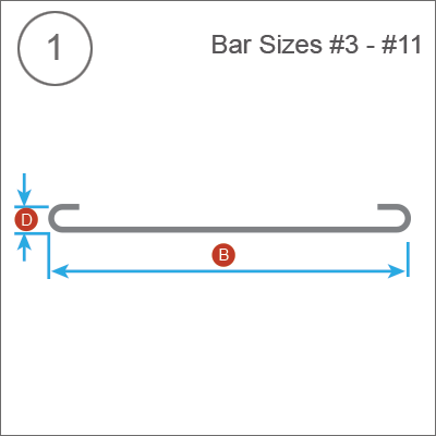
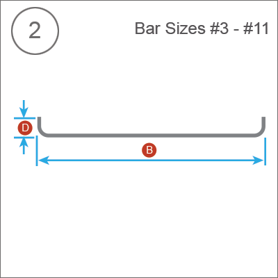
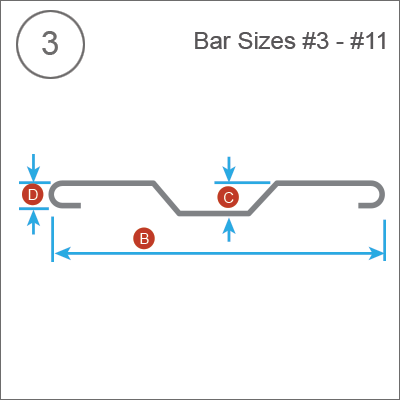
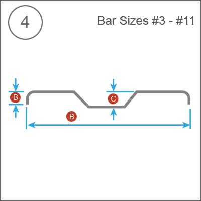
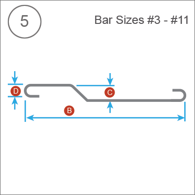
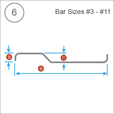
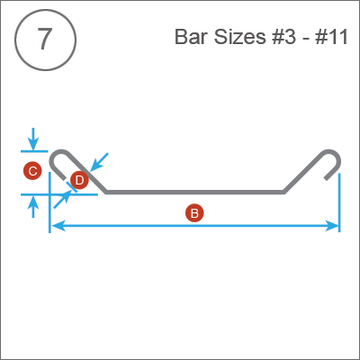
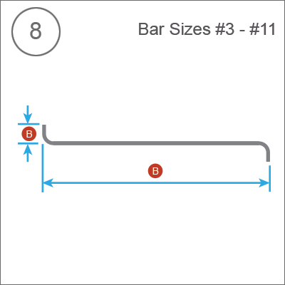
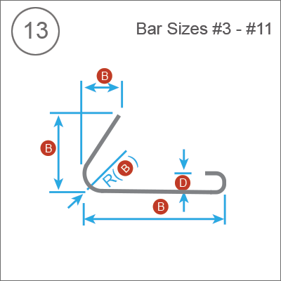
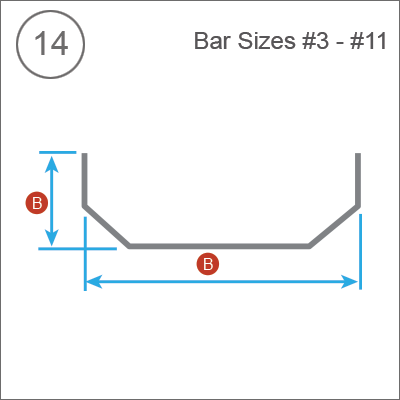
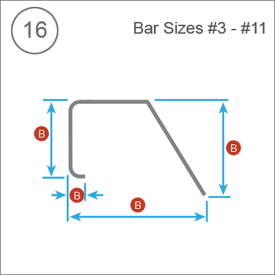
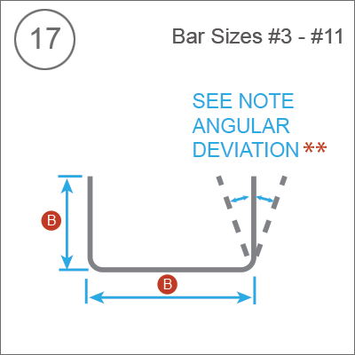
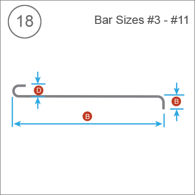
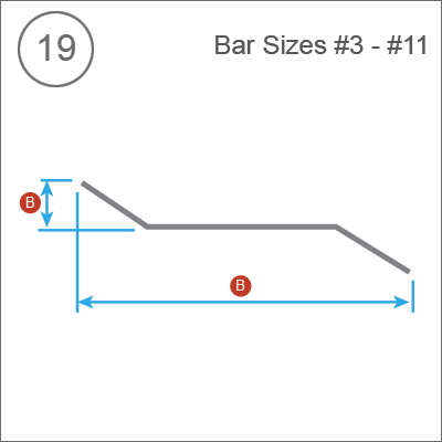
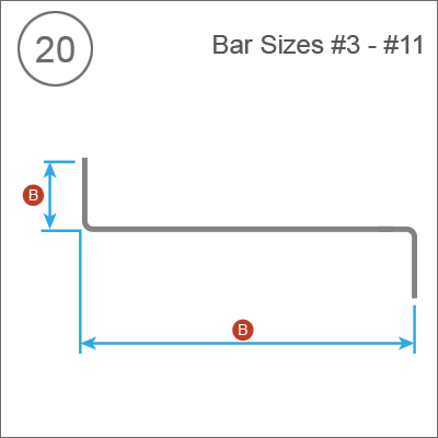
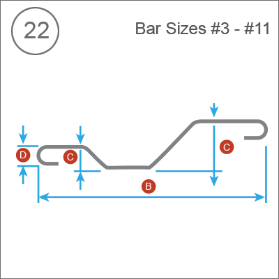
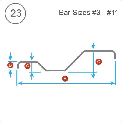
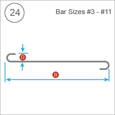
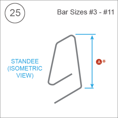
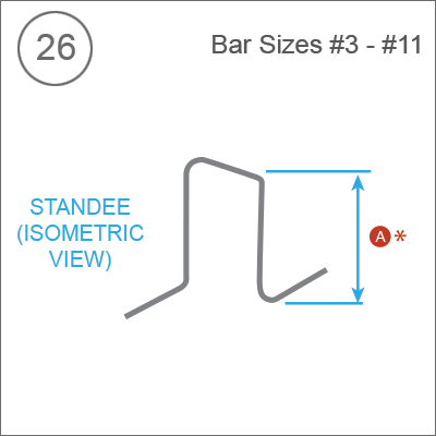
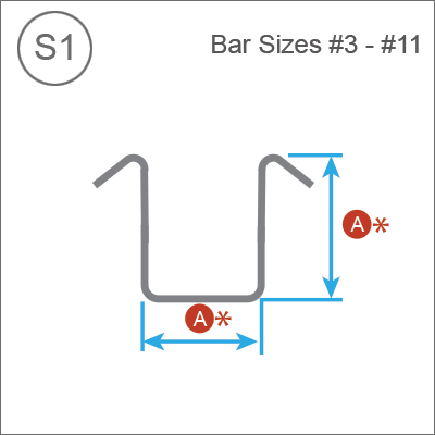
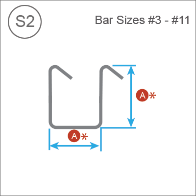
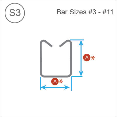
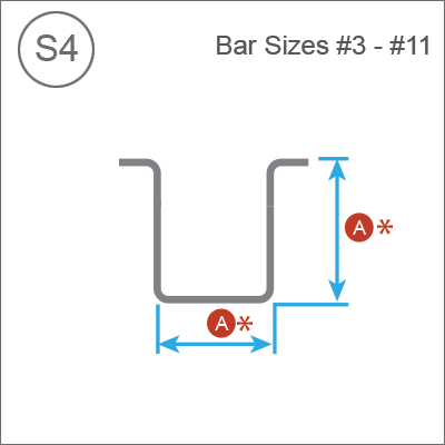
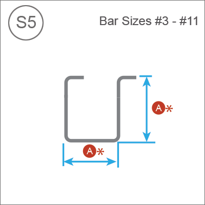
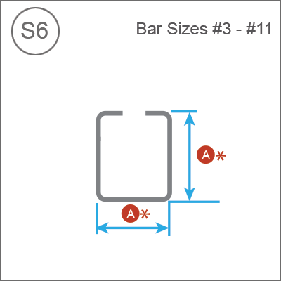
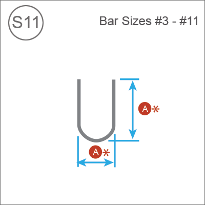
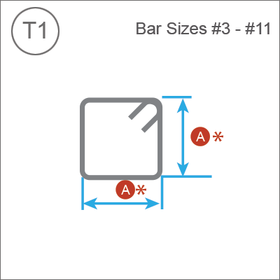
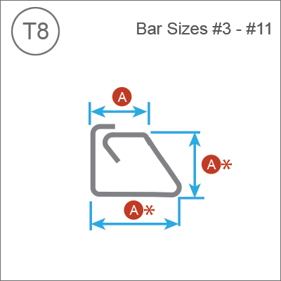
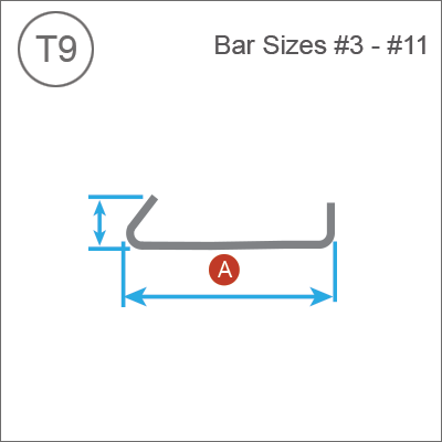


Bar Sizes #3 and #11 Legend and Notes
Legend
 |
± ½ inch for bar sizes #3, #4, and #5 with lengths < 12-00 feet. |
 |
± 1 inch for bar sizes #3, #4, and #5 with lengths ≥ 12-00 feet. |
|
± 1 inch for bar sizes #6, #7, and #8. |
 |
± 1 inch. |
 |
+ 0, - ½ inch. |
 |
± ½ inch. |
 |
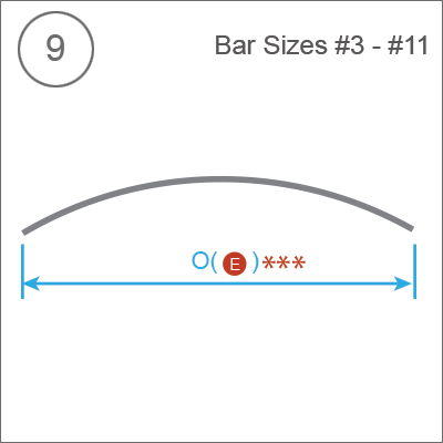
± 1.5% x O dimension, ≥ ± 2 inches. |
 |
- 1 inch for lap splice. |
Notes
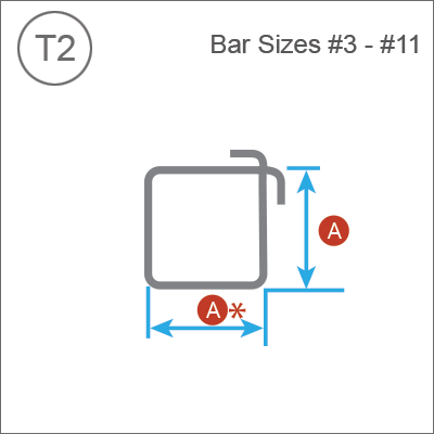
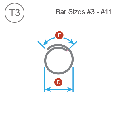
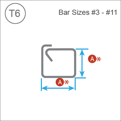
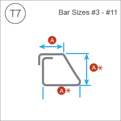
All tolerances single plane as shown.
* Dimensions on this line are to be within tolerance shown but are not to differ from the opposite parallel dimension by more than ½ inch.
** Angular Deviation - maximum ± 2½o or ±½ inch/foot but not less than ½ inch on all 90o hooks and bends.
*** If application of positive tolerance to Shape 9 results in a chord length not less than the arc or bar length, the bar may be shipped straight.
Tolerances for shapes S1 through S6, S11, T1 through T3, T6 through T9 apply to bar sizes #3 through #8 inclusive only.
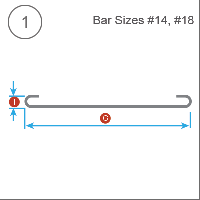
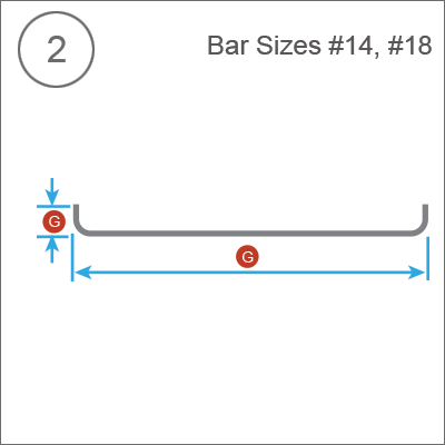
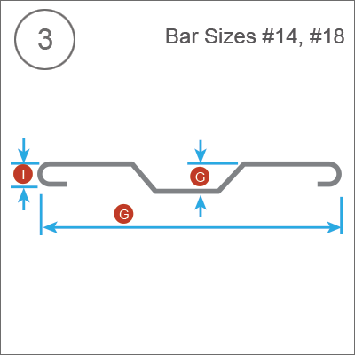
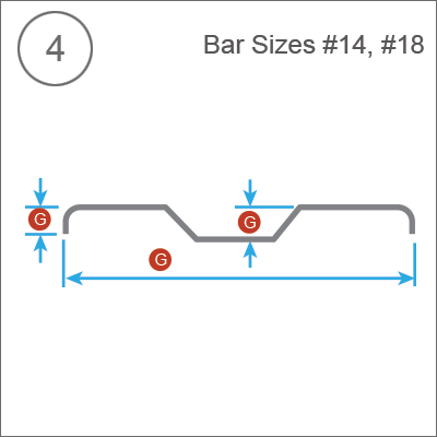
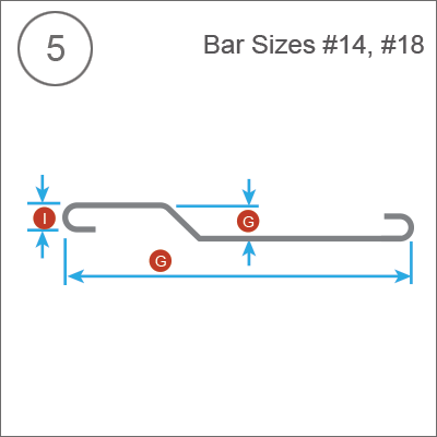
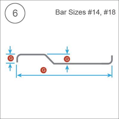
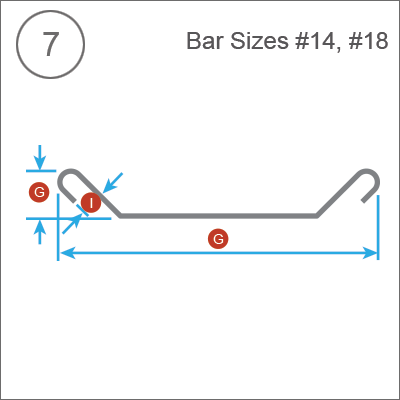
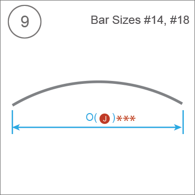
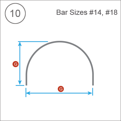
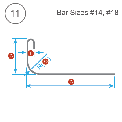
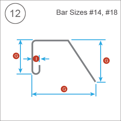
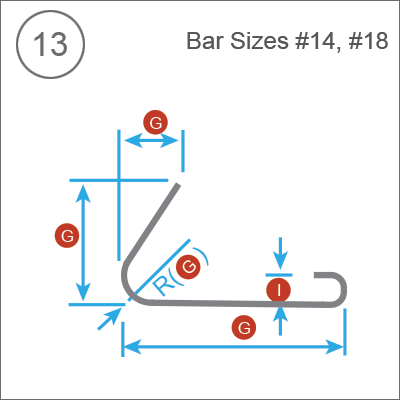
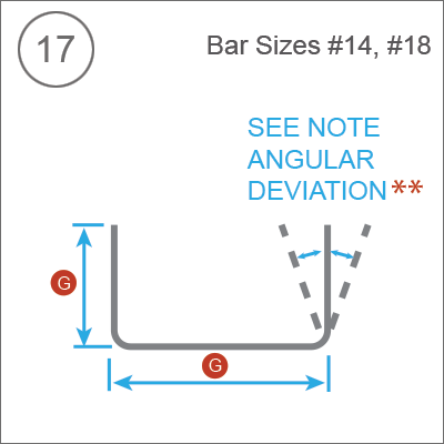
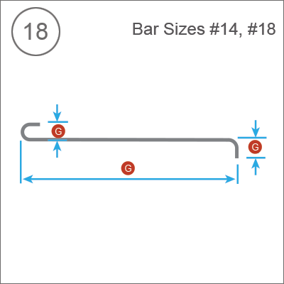
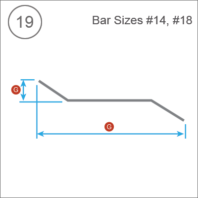
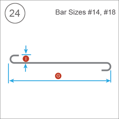
Bar Sizes #14 and #18 Legend Notes
Legend
| #14 | #18 | |
 |
± 2½ inches | ± 3½ inches |
 |
± 2 inches | ± 2 inches |
 |
± 1½ inches | ± 2 inches |
 |
± 2½ inches | ± 3½ inches |
Notes
All tolerances single plane as shown.
* Saw cut both ends - overall length = ½ inch.
** Angular Deviation - maximum ± 2½o or ±½ inch/foot on all 90o hooks and bends.
*** If application of positive tolerance to Shape 9 results in a chord length not less than the arc or bar length, the bar may be shipped straight.
Tolerances for shapes S1 through S6, S11, T1 through T3, T6 through T9 apply to bar sizes #3 through #8 inclusive only.
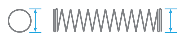
Tolerance for Fabricated Spiral Diameter
| ≤18" | >18, ≤30" | >30", ≤48" | >48", ≤66" | |
| #3 | ±½" | ±½" | +1", -0" | Not Recommended |
| #4 | ±½" | ±½" | +1", -0" | Not Recommended |
| #5 | ±½" | ±½" | +1", -0" | +2", -0" |
| #6 | Not available | ±½" | +1", -0" | +2", -0" |
| #7 | Not available | Not available | +1", -0" | +2", -0" |
| #8 | Not available | Not available | Not available | +2", -0" |
| >66", ≤84" | >84", ≤102" | >102" | |
| #3 | Not recommended | Not recommended | Not recommended |
| #4 | Not recommended | Not recommended | Not recommended |
| #5 | +3", -0" | +4", -0" | +5", -0" |
| #6 | +3", -0" | +4", -0" | +5", -0" |
| #7 | +3", -0" | +4", -0" | +5", -0" |
| #8 | +3", -0" | +4", -0" | +5", -0" |
Notes
- The tolerances shown are for fabricated spiral reinforcing only and should not be used to measure final field tolerance for an assembled unit. The final field tolerance for the diameter of an assembled unit is ±1 inch.
- #3 bars are not recommended for use in spirals larger than 30 inches.
- #4 bars are no recommended for use in sprials larger than 48 inches.
- Special consideration must be used when loading, unloading, and handling large diameter spirals and ties to prevent misshaping the fabricated diameter.
- The fabricator must take the number of turns in the spiral into consideration to ensure that on large diameter spirals there is enough material to complete the finished length of the spiral.
- The contractor, fabricator, and placer must coordinate and make arrangements for additional material required for bracing and supporting the assembled unit to maintain the required diameter.