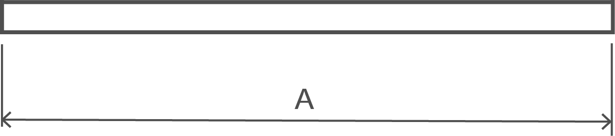
BSI Typical Bend Shapes
| Shape Code | 00 |
|---|---|
 |
|
| Total Length of bar. L measured along center line. | A |
| Shape Code | 01 |
|---|---|
|
|
| Total Length of bar. L measured along center line. | A - Stock Lengths. See Note 4. |
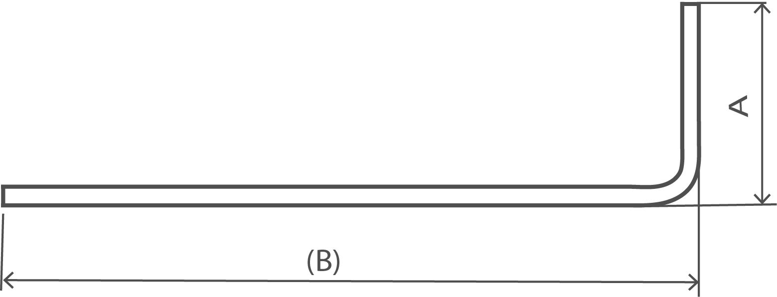
| Shape Code | 11 |
|---|---|
 |
|
| Total Length of bar. L measured along center line. | A + (B) - 0.5r - d |
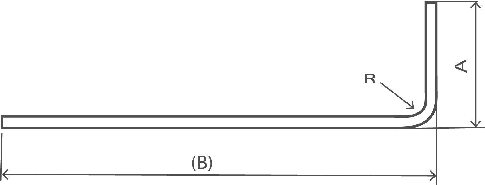
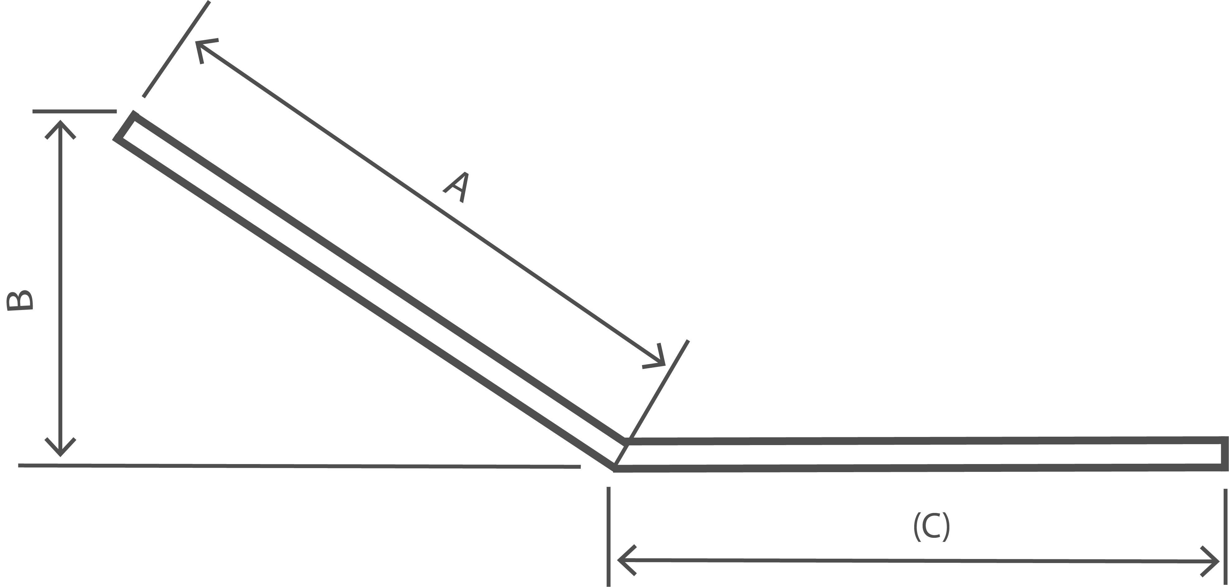
| Shape Code | 12 |
|---|---|
 |
|
| Total Length of bar. L measured along center line. |
A + (B) - 0.43R - 1.2d Neither A nor B shall be less than (R+6d) |
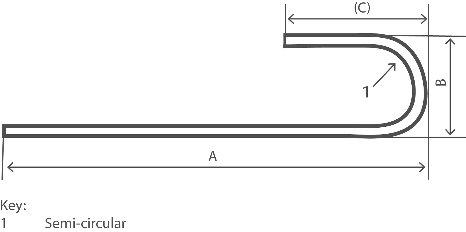
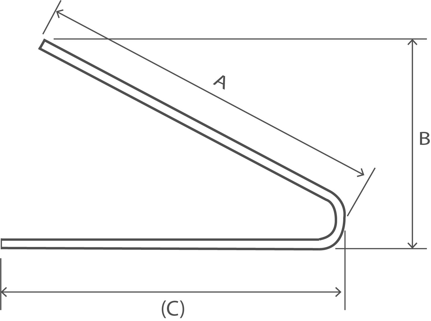
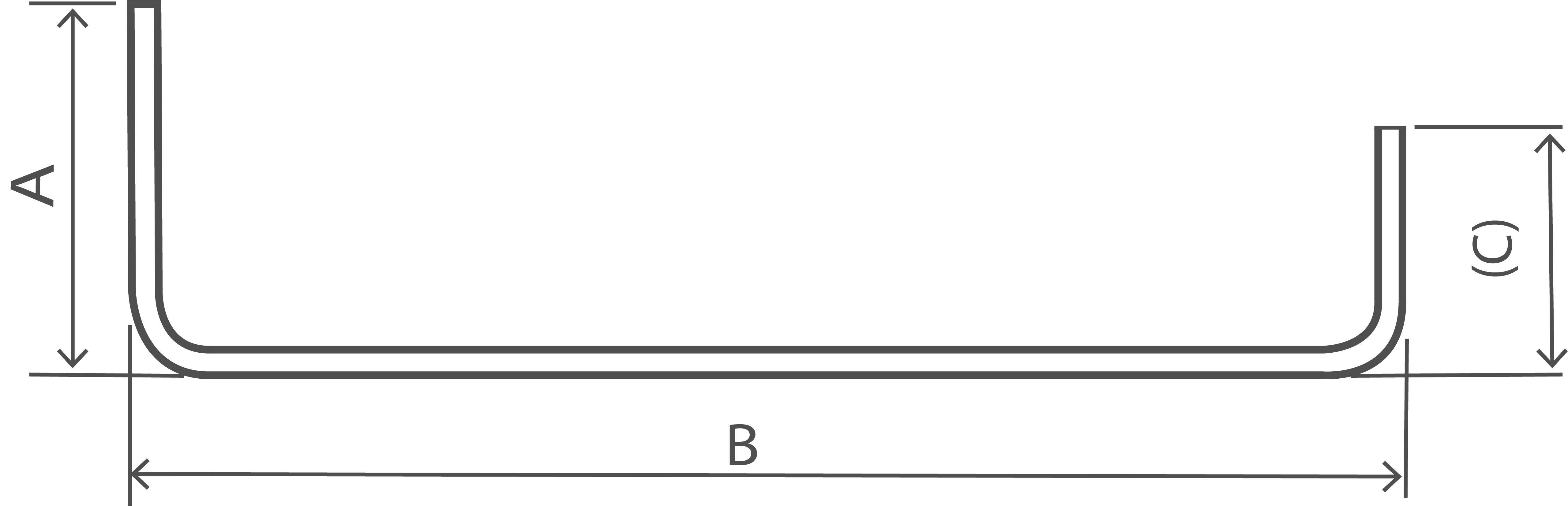
| Shape Code | 13 |
|---|---|
 |
|
| Total Length of bar. L measured along center line. |
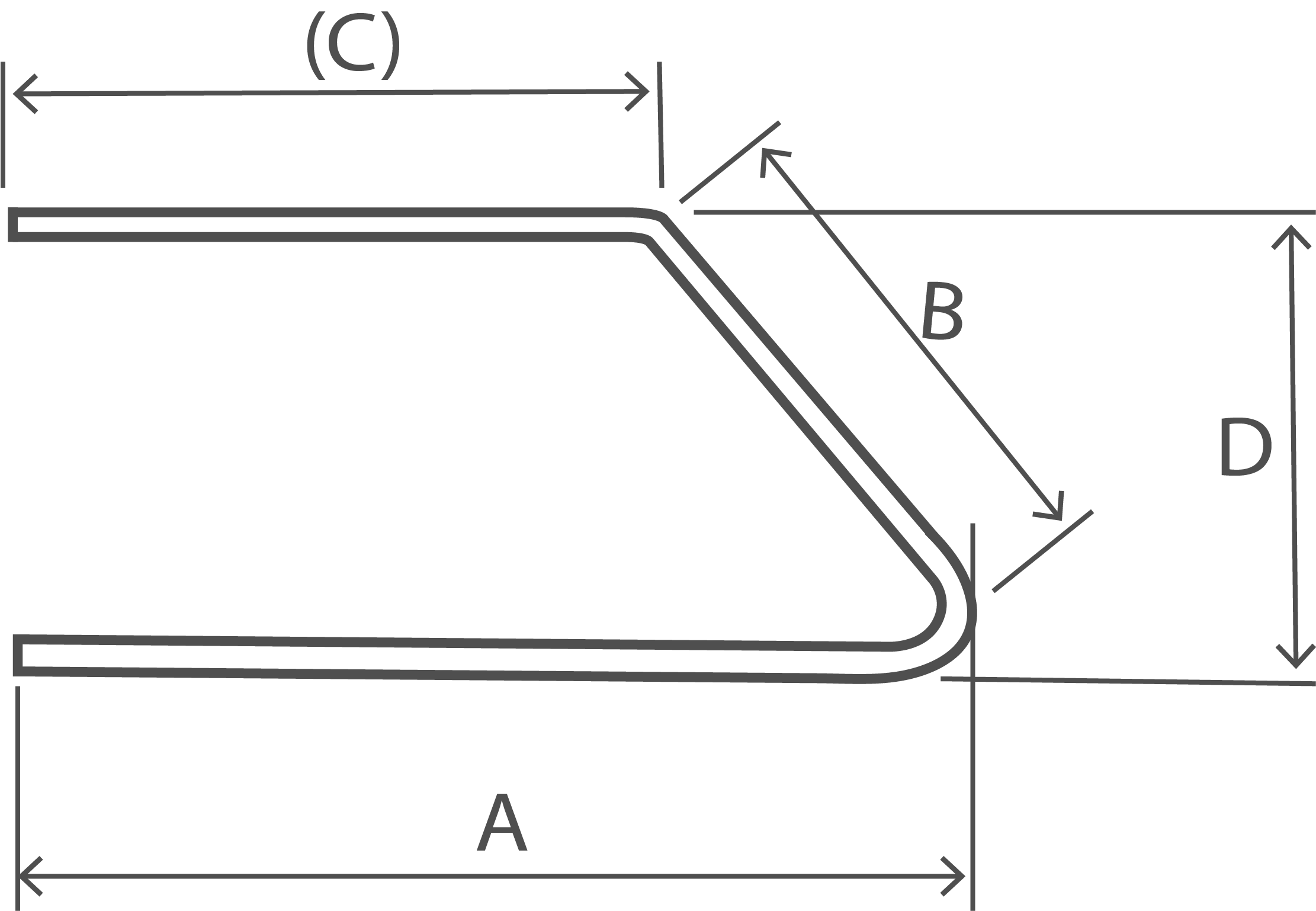
A + 0.57B + (C) - 1.6d B shall not be less than 2(r+d) |
| Shape Code | 14 |
|---|---|
 |
|
| Total Length of bar. L measured along center line. | A + (C) - 4d |
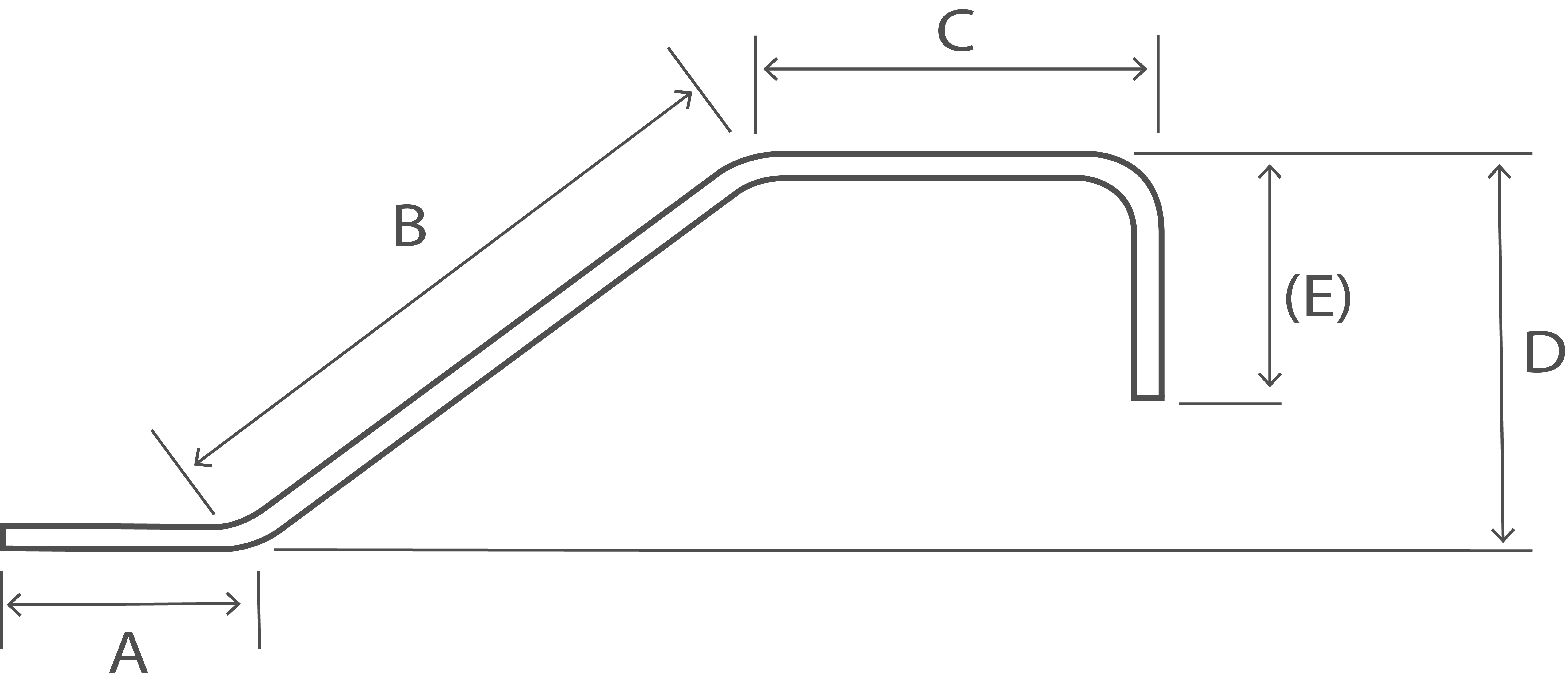
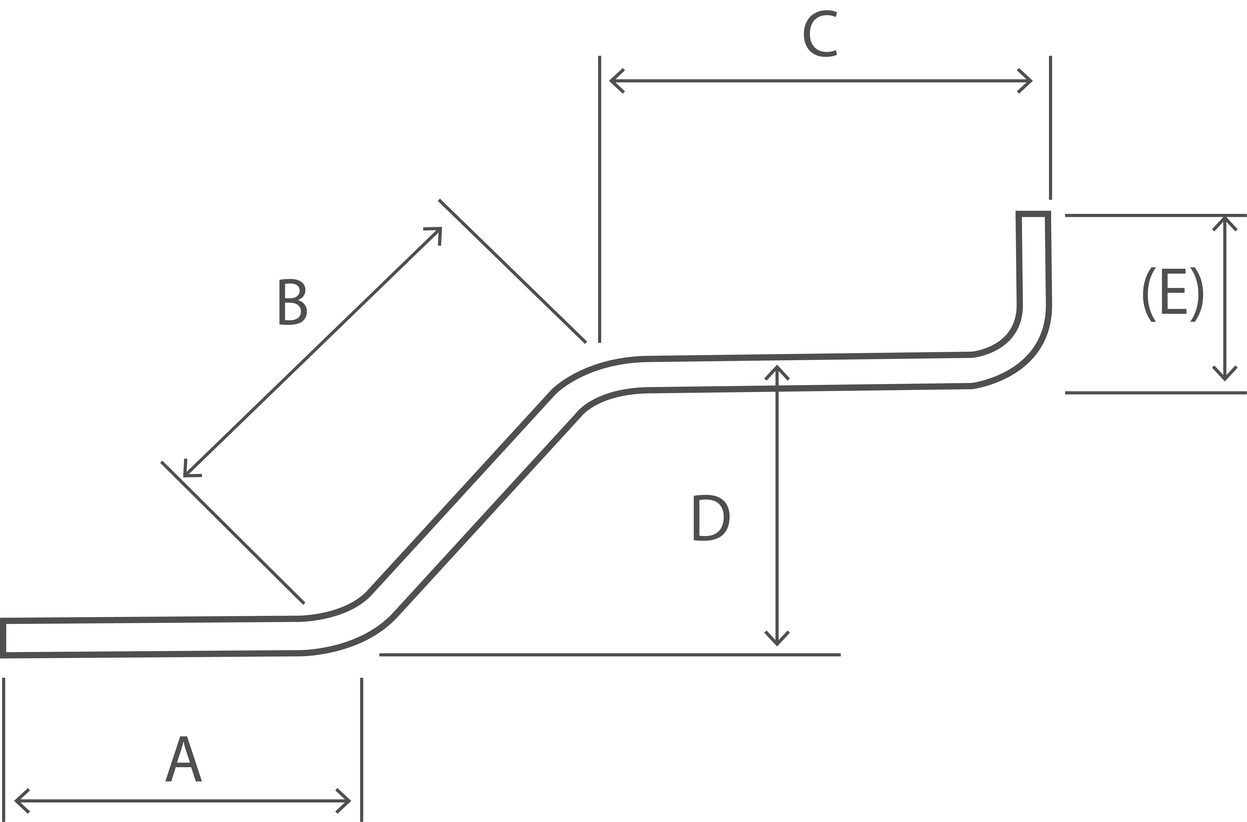
| Shape Code | 15 |
|---|---|
 |
|
| Total Length of bar. L measured along center line. | A + (C) |
| Shape Code | 21 |
|---|---|
 |
|
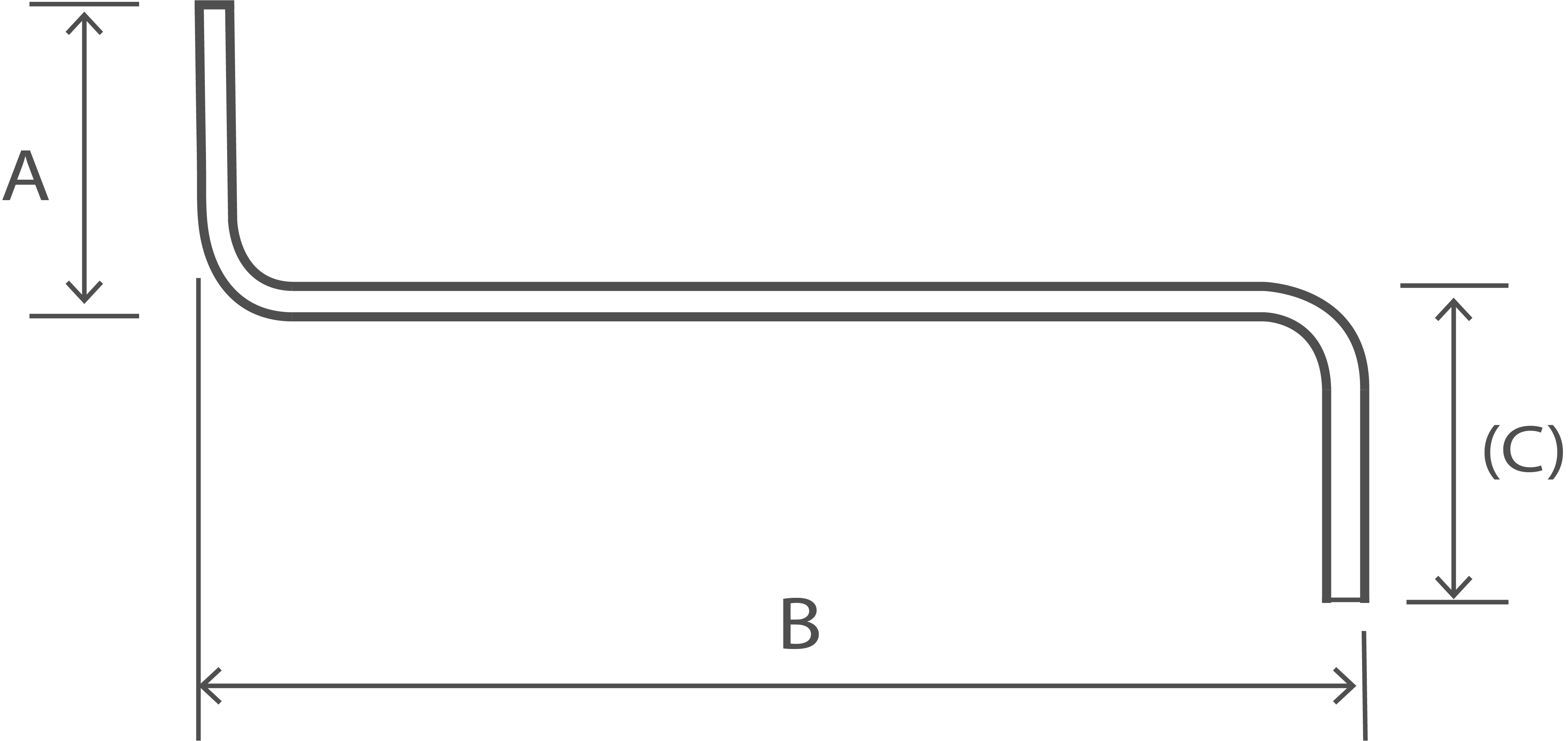
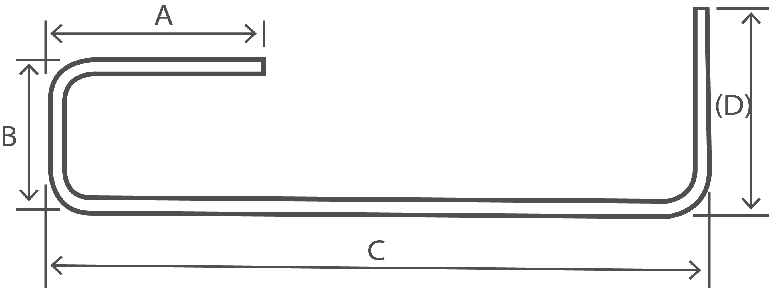
| Total Length of bar. L measured along center line. | A + B + (C) - r - 2d |
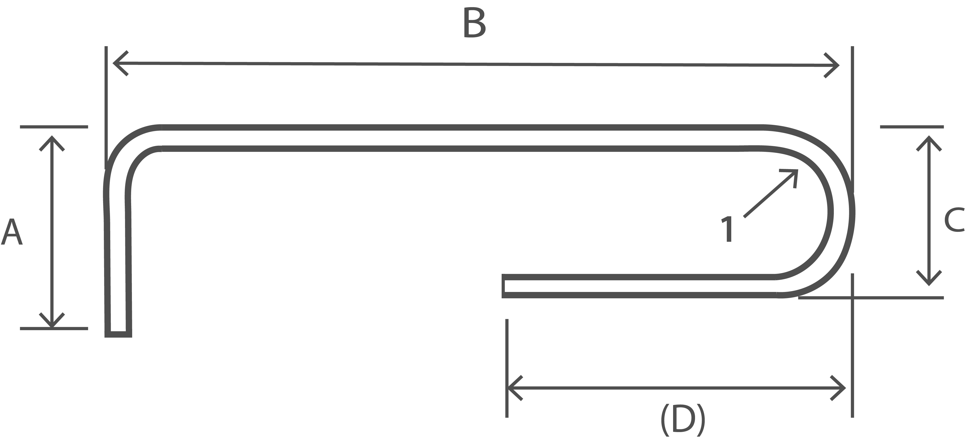
| Shape Code | 22 |
|---|---|
 |
|
| Total Length of bar. L measured along center line. |
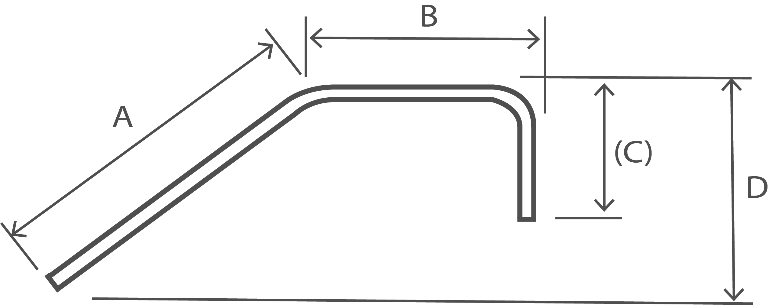
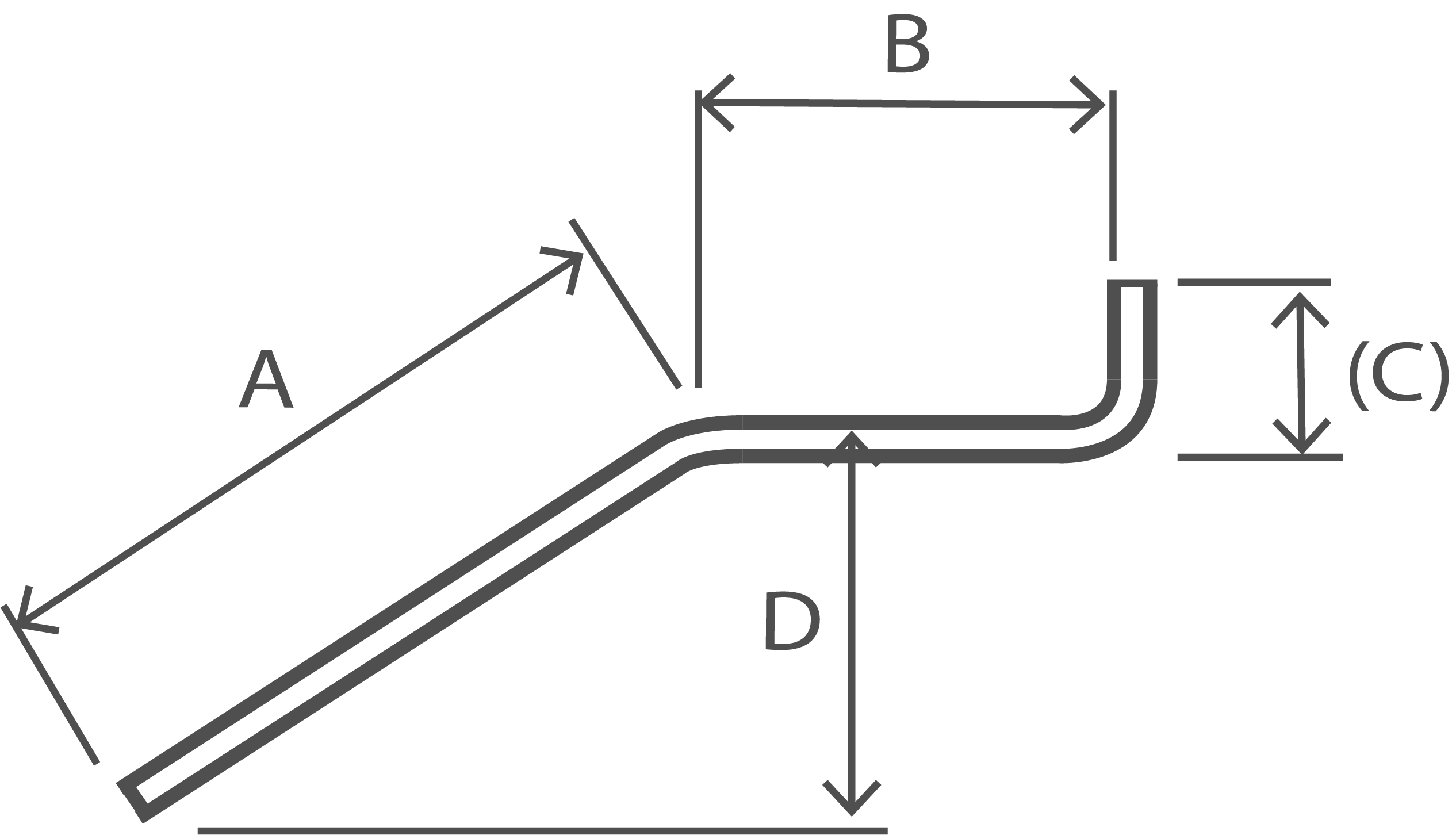
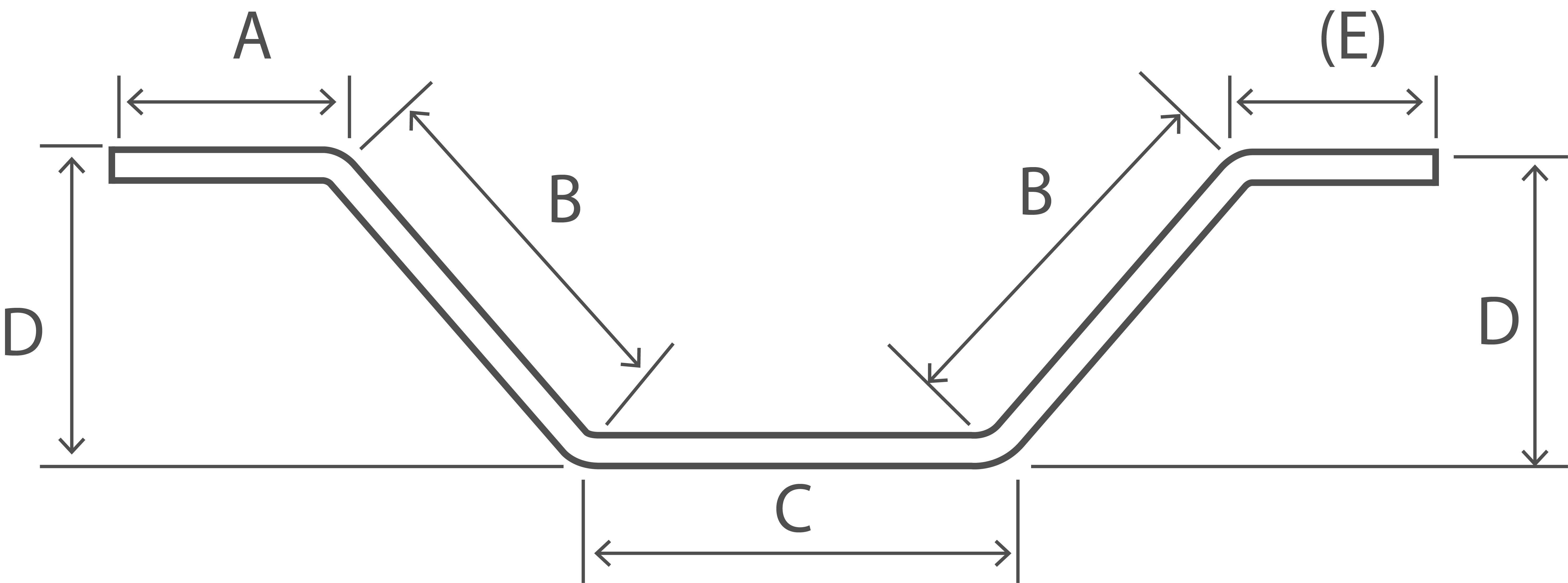
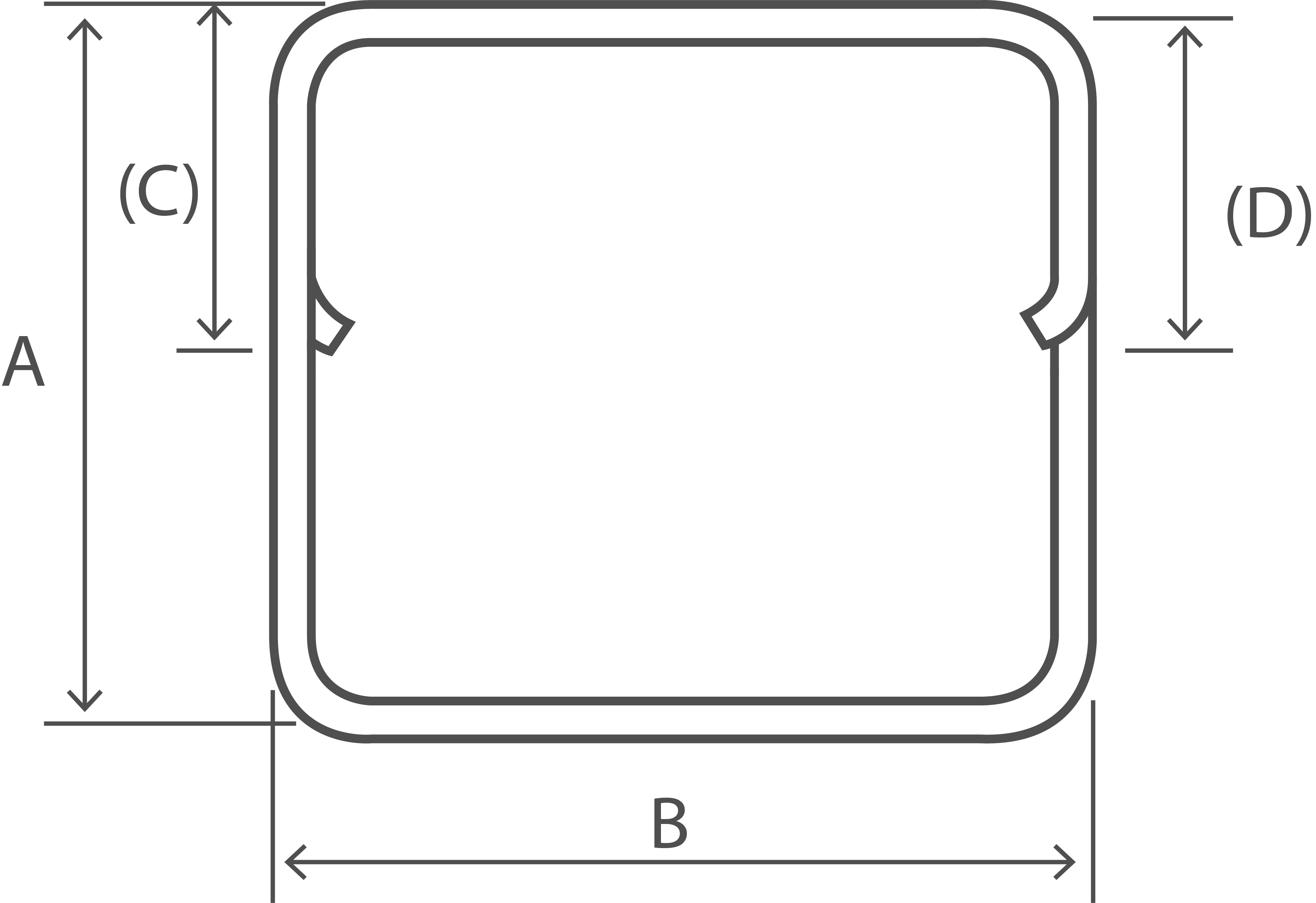
A + B + C + (D) - 1.5r - 3d C shall not be less than 2(r+d). (D) shall not be less than C/2 +5d |
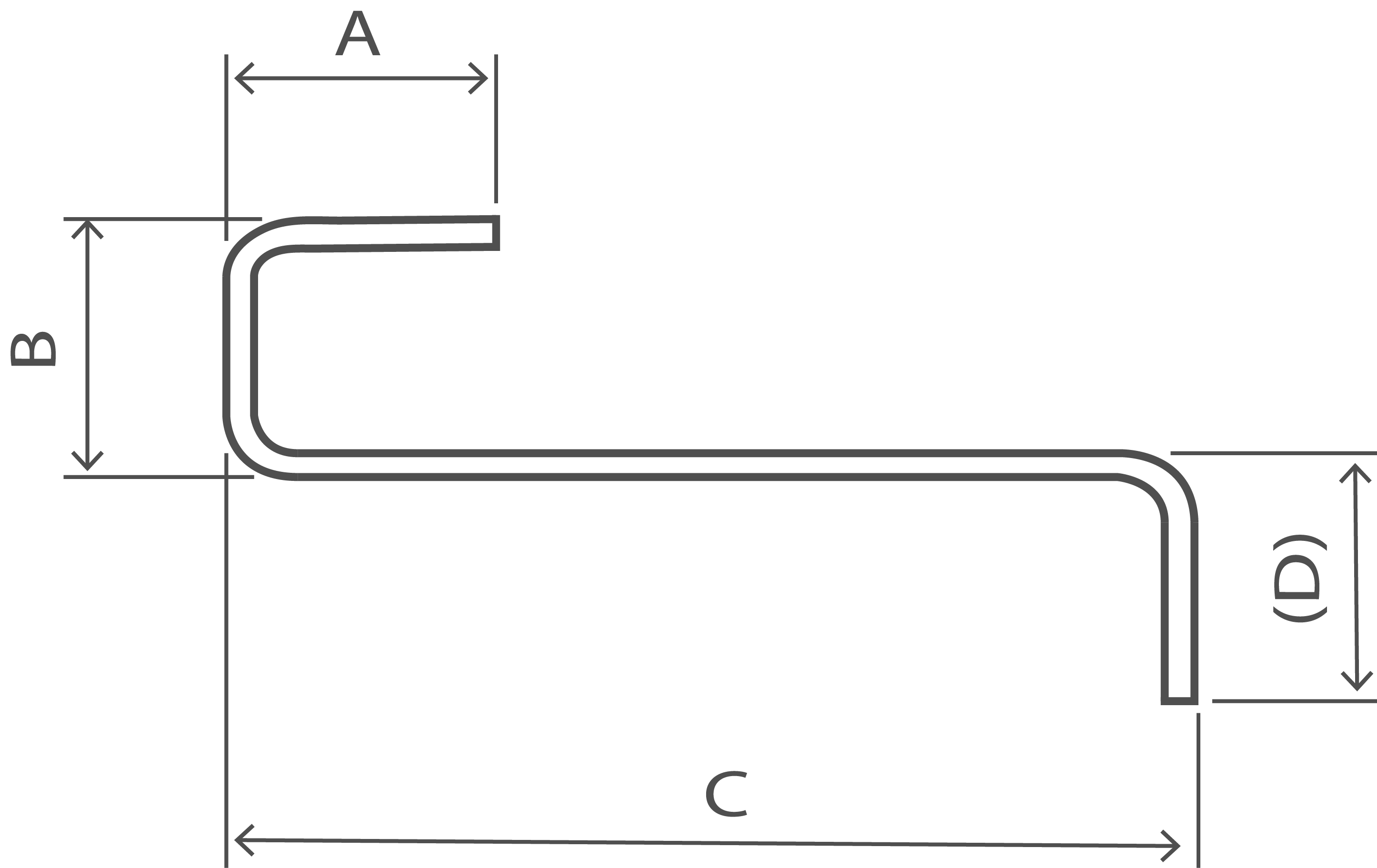
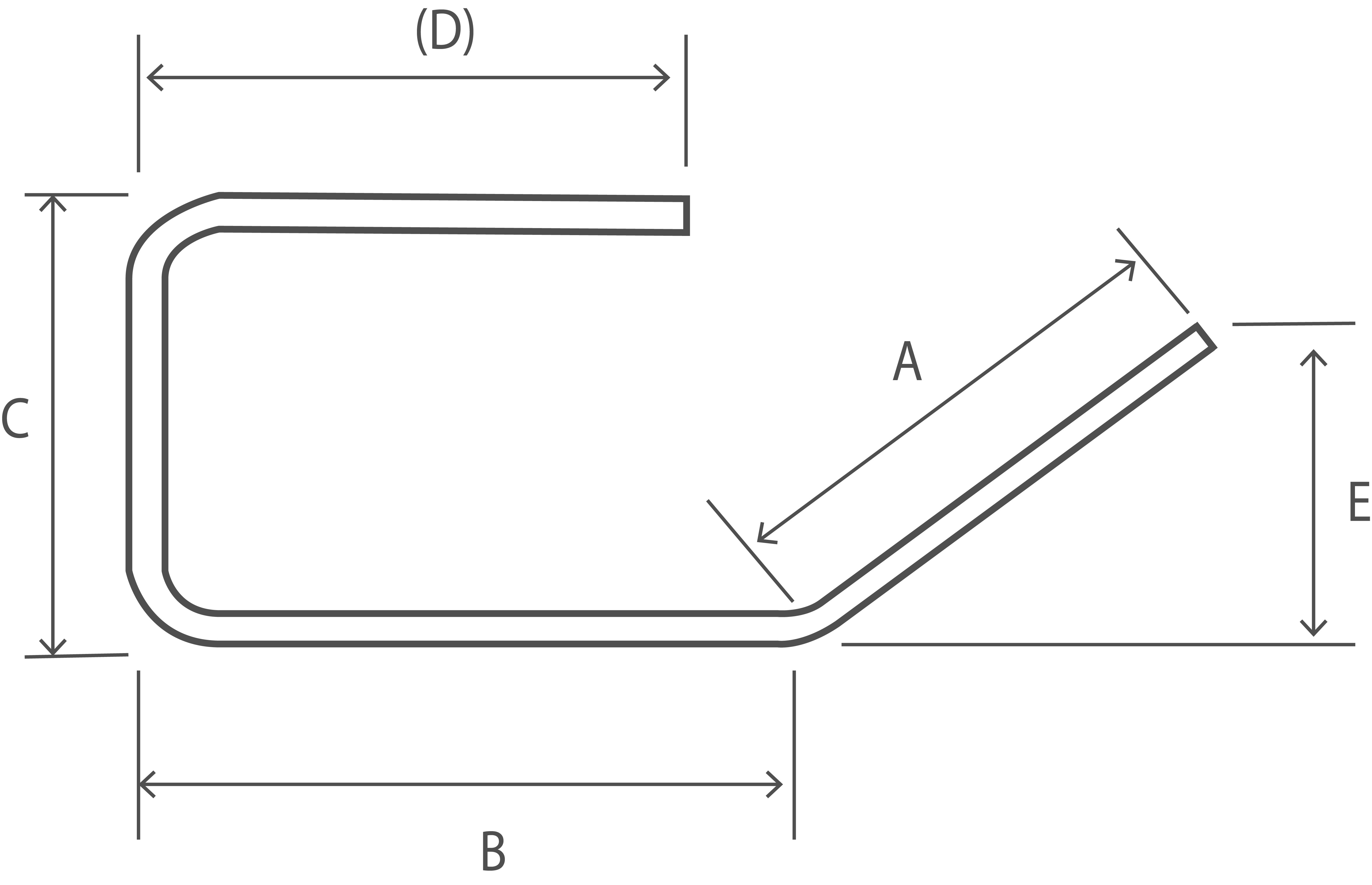
| Shape Code | 23 |
|---|---|
 |
|
| Total Length of bar. L measured along center line. |
A + B + (C) - r - 2d |
| Shape Code | 24 |
|---|---|
 |
|
| Total Length of bar. L measured along center line. |
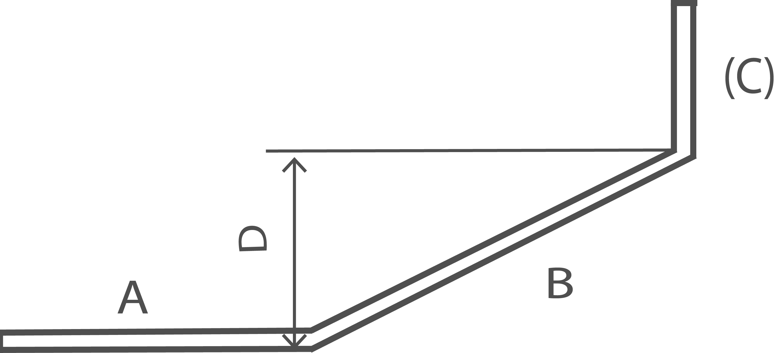
A + B + (C) A and (C) are at 90° to one another |
| Shape Code | 25 |
|---|---|
 |
|
| Total Length of bar. L measured along center line. |
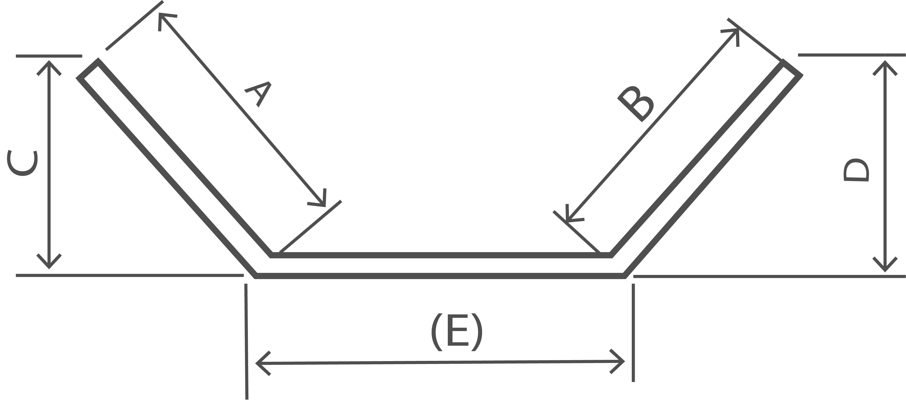
A + B + (E) If E is the critical dimension, schedule a 99 and specify A or B as the free dimension. See Note 1. |
| Shape Code | 26 |
|---|---|
 |
|
| Total Length of bar. L measured along center line. |
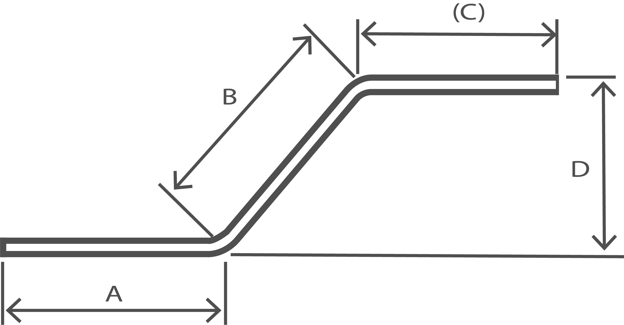
A + B + (C) |
| Shape Code | 27 |
|---|---|
 |
|
| Total Length of bar. L measured along center line. |
A + B + (C) - 0.5r - d |
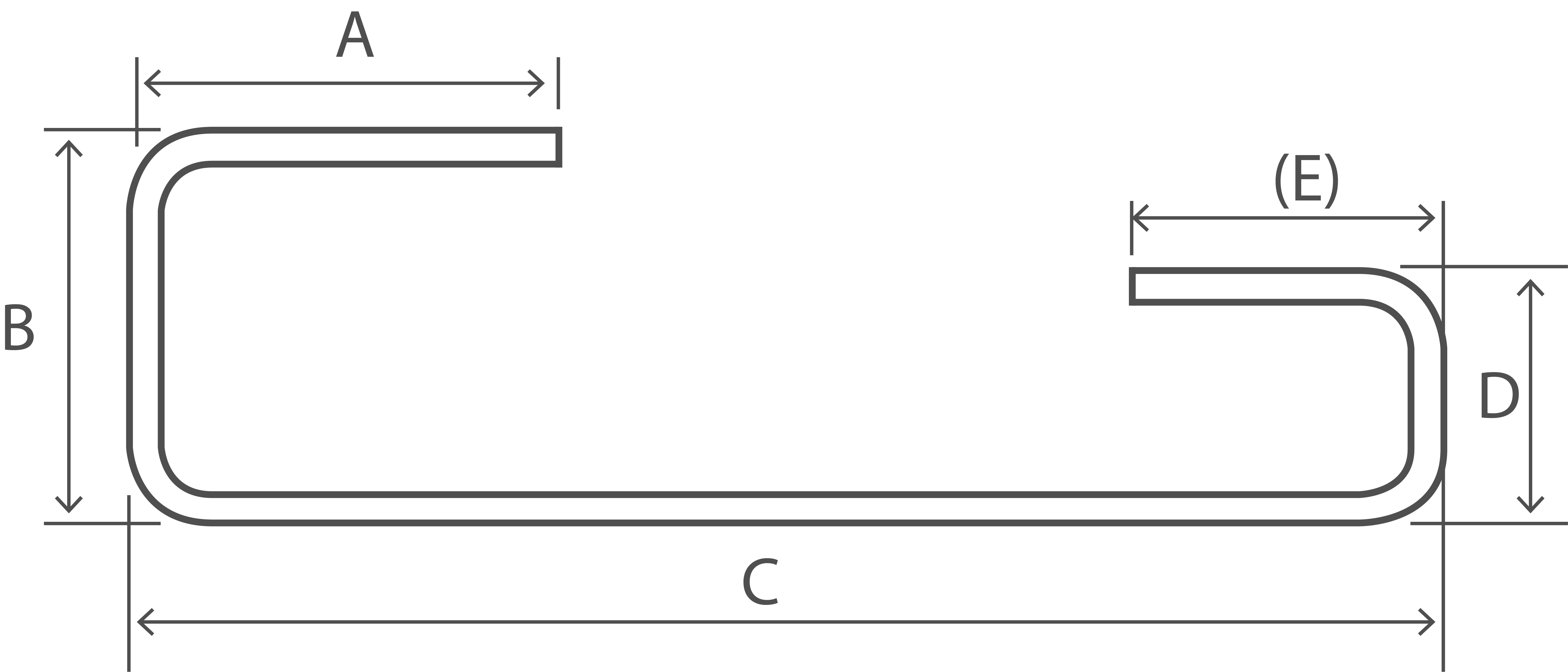
| Shape Code | 28 |
|---|---|
 |
|
| Total Length of bar. L measured along center line. |
A + B + (C) - 0.5r - d If E is the critical dimension, schedule a 99 and specify A or B as the free dimension. See Note 1. |
| Shape Code | 29 |
|---|---|
 |
|
| Total Length of bar. L measured along center line. |
A + B + C + (D) - r - 2d |
| Shape Code | 31 |
|---|---|
 |
|
| Total Length of bar. L measured along center line. |
A + B + C + (D) - 1.5r - 3d |
| Shape Code | 32 |
|---|---|
 |
|
| Total Length of bar. L measured along center line. |
A + B + C + (D) - 1.5r - 3d If E is the critical dimension, schedule a 99 and specify A or B as the free dimension. See Note 1. |
| Shape Code | 33 |
|---|---|
 |
|
| Total Length of bar. L measured along center line. |
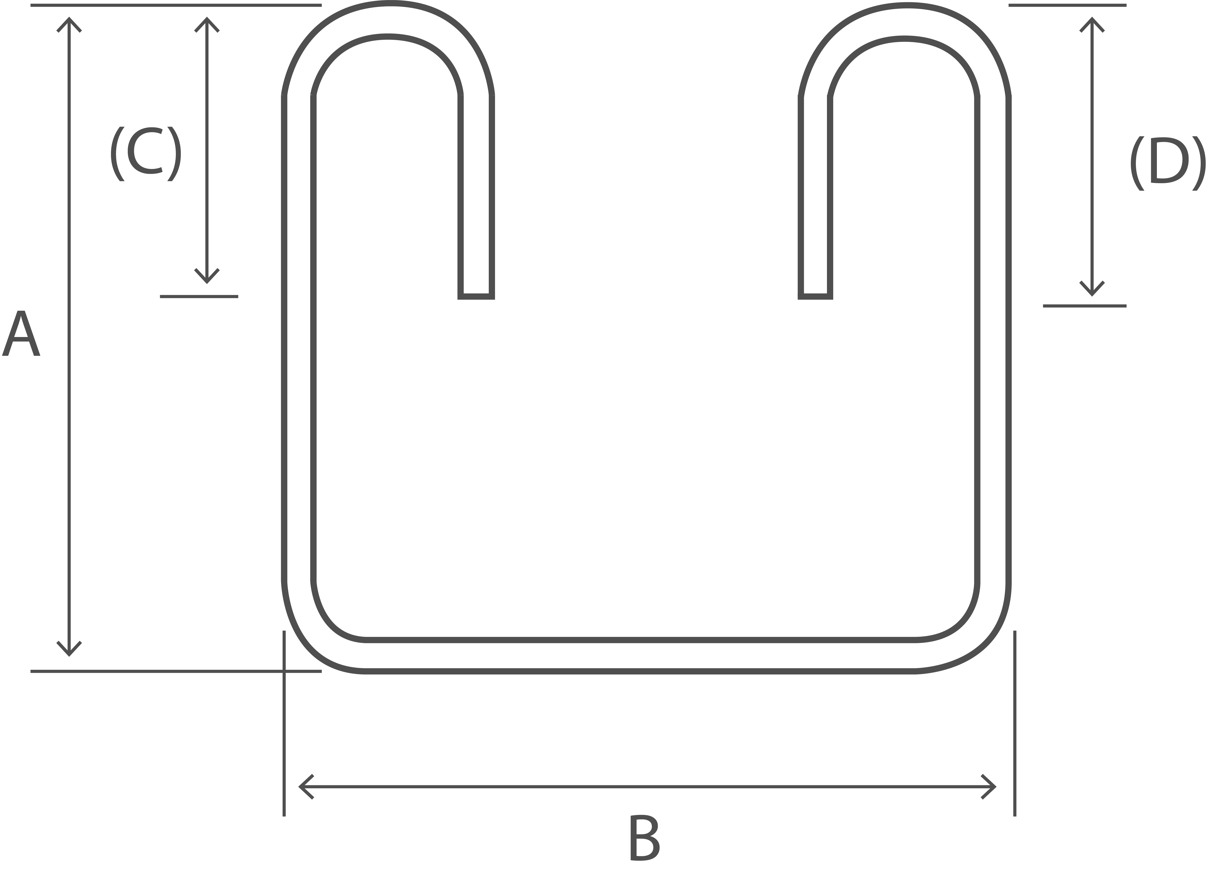
2A + 1.7B + 2(C) - 4d A shall not be less than 12d + 30 B shall not be less than 2(r + d)/p> (C) shall not be less than B/2 + 5d See Note 3 |
| Shape Code | 34 |
|---|---|
 |
|
| Total Length of bar. L measured along center line. |
A + B + C + (E) - 0.5r - d See Note 1 |
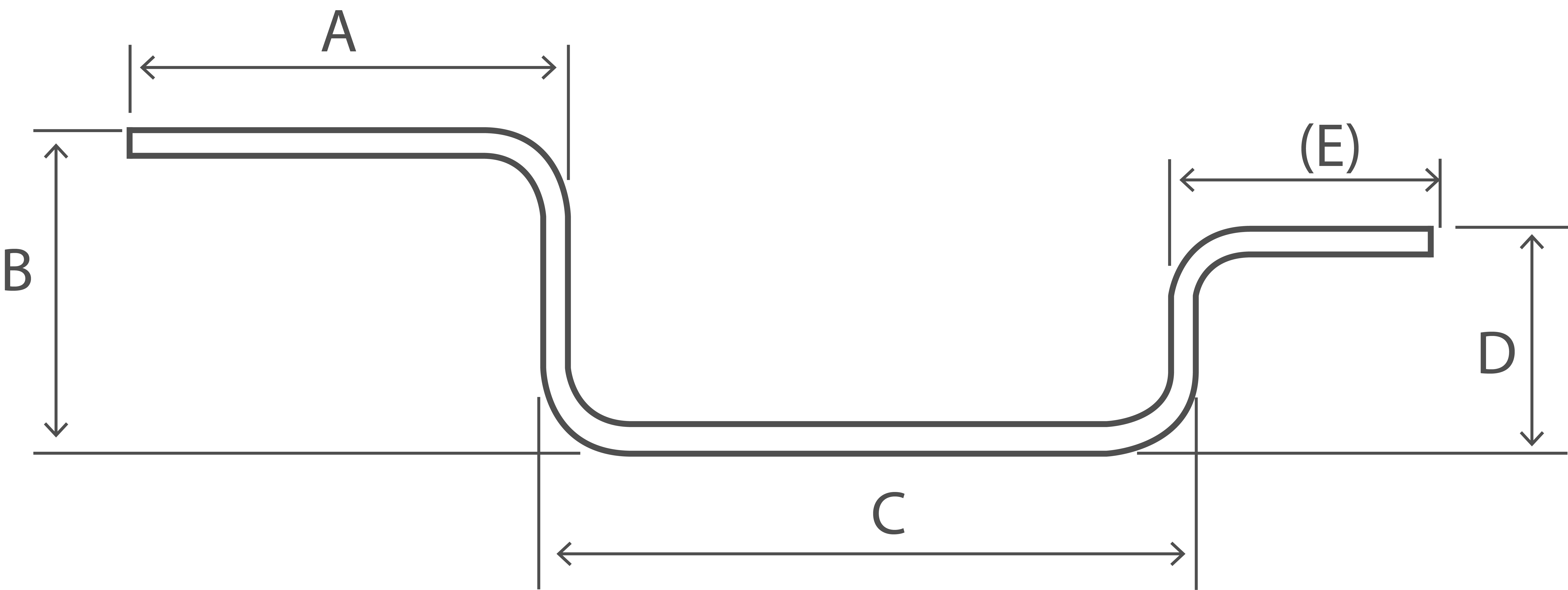
| Shape Code | 35 |
|---|---|
 |
|
| Total Length of bar. L measured along center line. |
A + B + C + (E) - 0.5r - d See Note 1 |
| Shape Code | 36 |
|---|---|
 |
|
| Total Length of bar. L measured along center line. |
A + B + C + (D) - r - 2d See Note 1 |
| Shape Code | 41 |
|---|---|
 |
|
| Total Length of bar. L measured along center line. |
A + B + C + D + (E) - 2r - 4d May also be used for flag link viz: 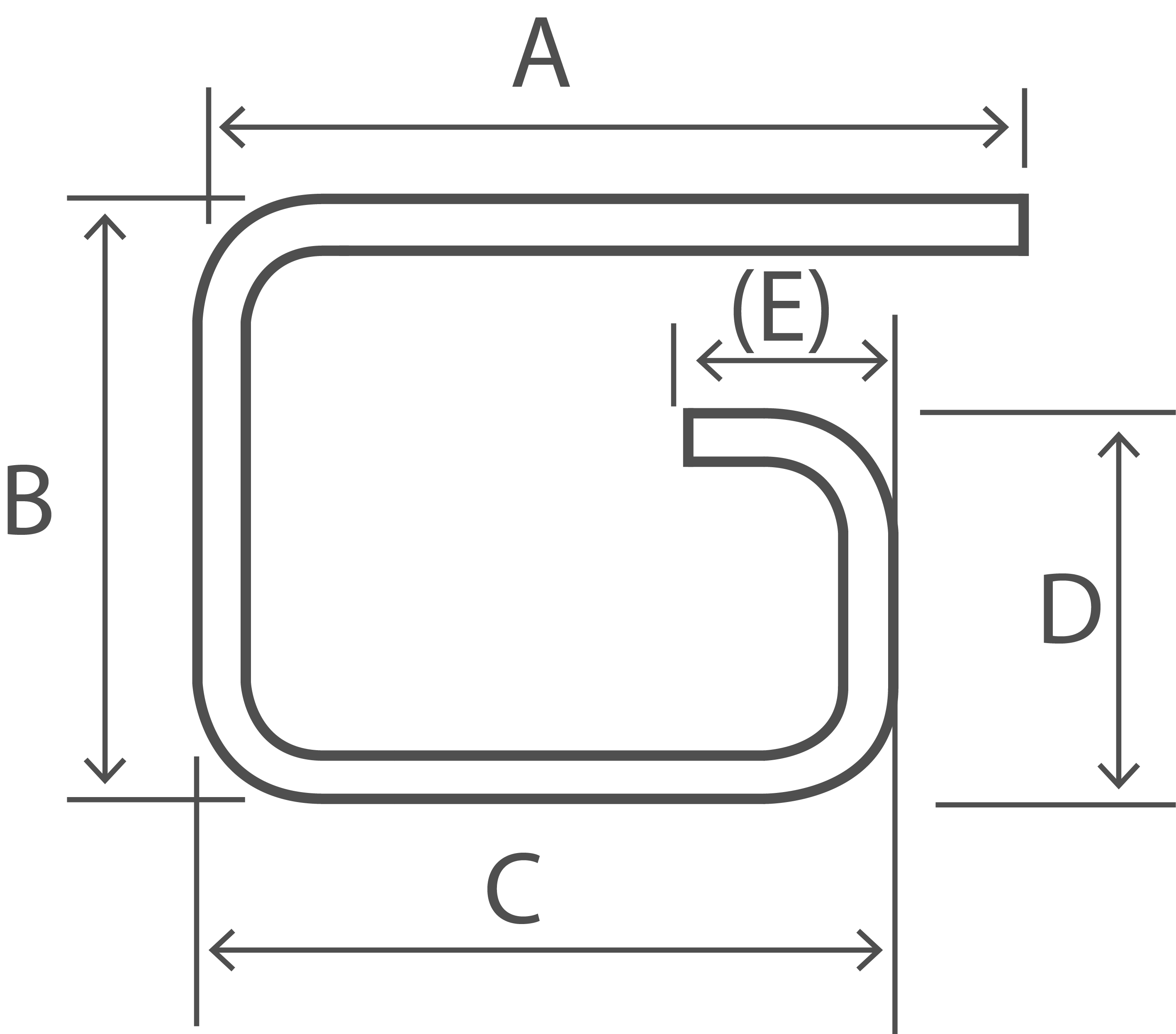
|
| Shape Code | 44 |
|---|---|
 |
|
| Total Length of bar. L measured along center line. |
A + B + C + D + (E) - 2r - 4d |
| Shape Code | 46 |
|---|---|
 |
|
| Total Length of bar. L measured along center line. |
A + 2B + C + (E) See Note 1 |
| Shape Code | 47 |
|---|---|
 |
|
| Total Length of bar. L measured along center line. |
2A + B + 2C + 1.5r - 3d (C) and (D) shall be equal and less than A Where (C) and (D) are to be minimized, the following formula may be used: L = 2A + 2B + max(16d, 160) |
| Shape Code | 51 |
|---|---|
 |
|
| Total Length of bar. L measured along center line. |
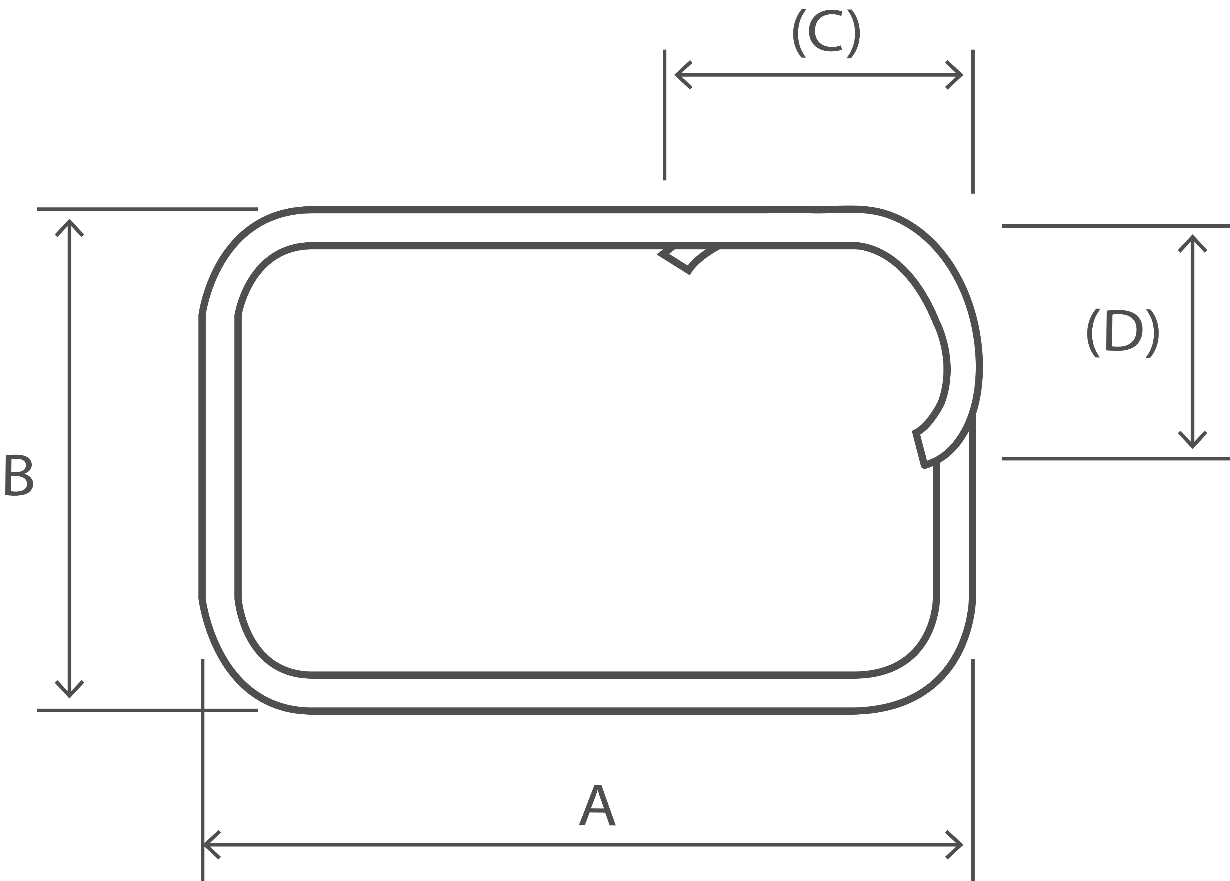
2(A + B + (C)) - 2.5r - 5d (C) and (D) shall be equal and less than A and B Where (C) and (D) are to be minimized, the following formula may be used: L = 2A + 2B + max(16d, 160) |
| Shape Code | 56 |
|---|---|
 |
|
| Total Length of bar. L measured along center line. |
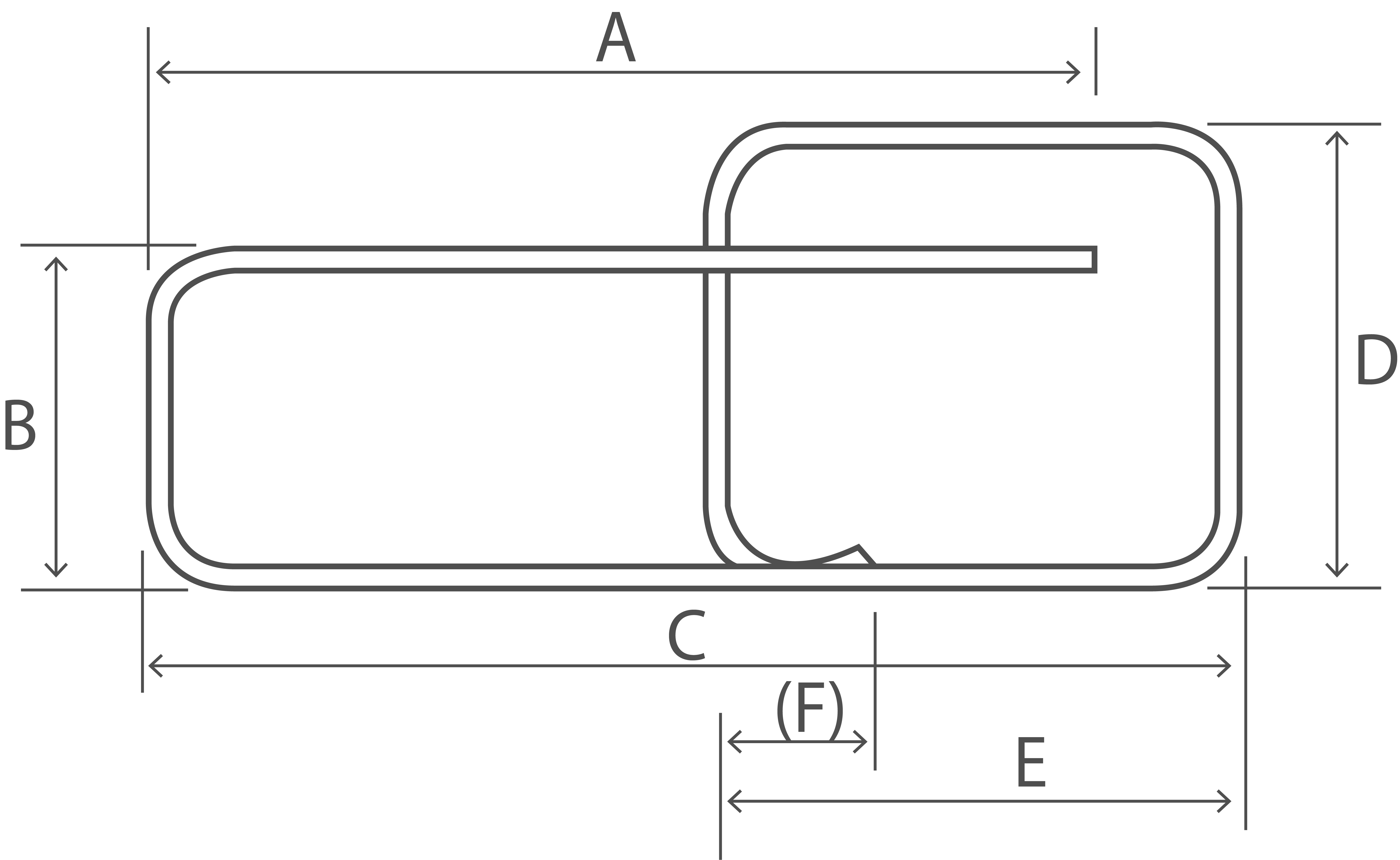
A + B + C + (D) + 2(E) - 2.5r - 5d (E) and (F) shall be equal and not more than B and C |
| Shape Code | 63 |
|---|---|
 |
|
| Total Length of bar. L measured along center line. |
2A + 3B + 2(C) -3r - 6d (C) and (D) shall be equal and less than A and B Where (C) and (D) are to be minimized, the following formula may be used: L = 2A + 3B + max(14d, 150) |
| Shape Code | 64 |
|---|---|
 |
|
| Total Length of bar. L measured along center line. |
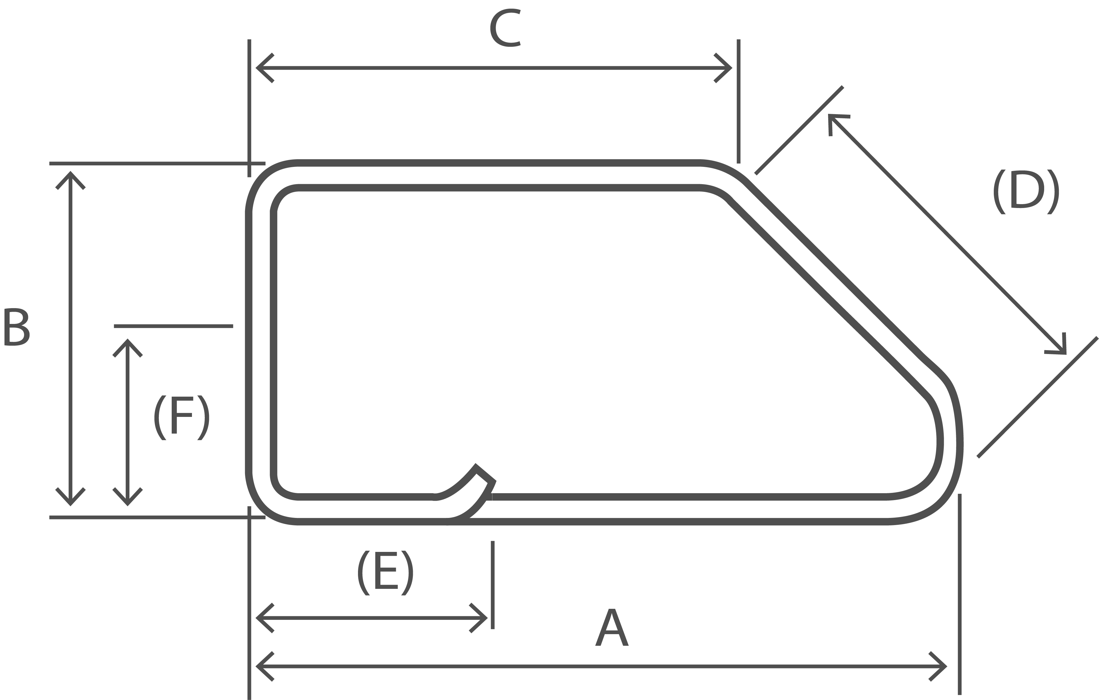
A + B + C + 2D + E + (F) - 3r - 6d See Note 2 |
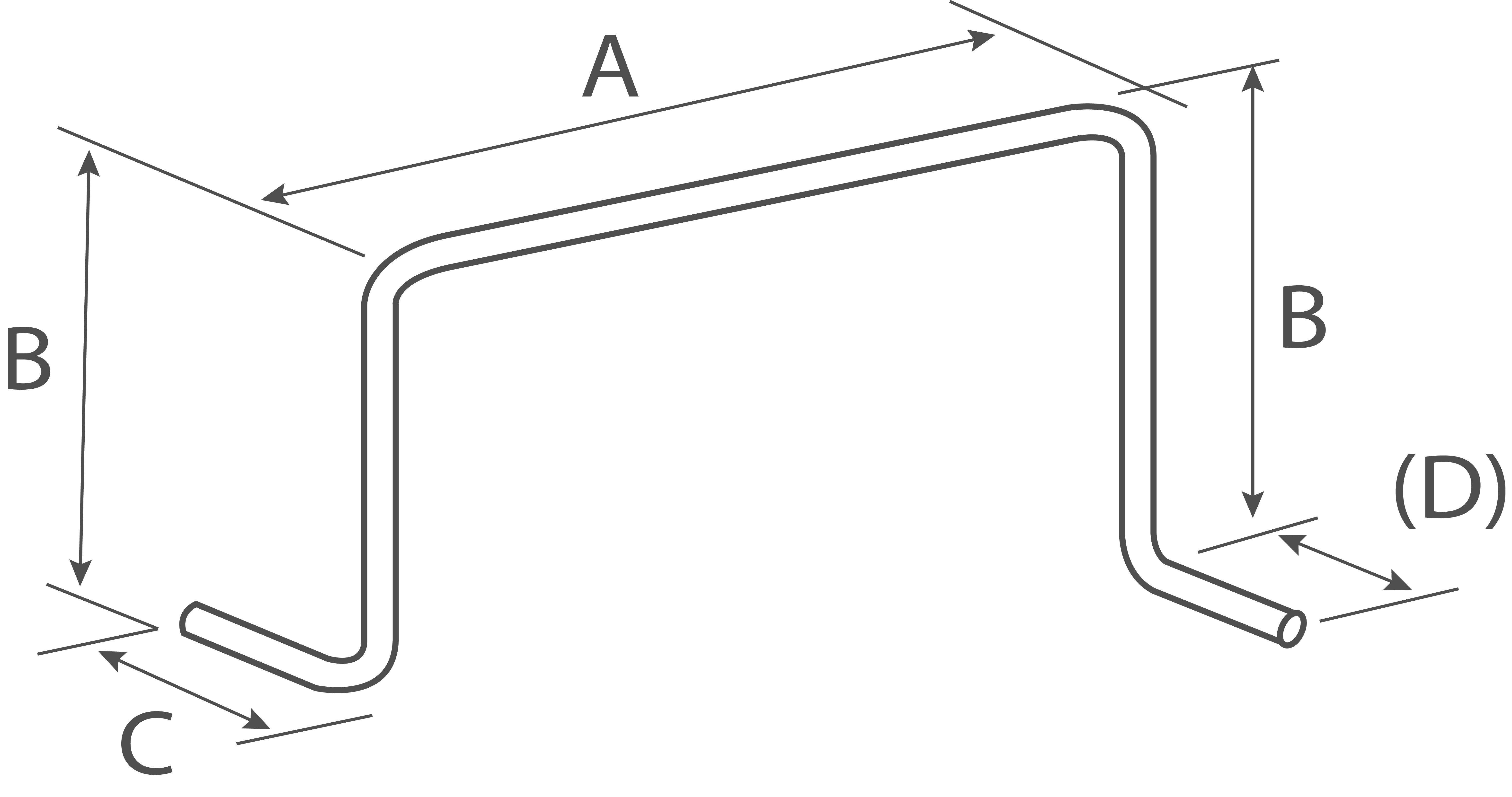
| Shape Code | 67 |
|---|---|
 |
|
| Total Length of bar. L measured along center line. |
A |
| Shape Code | 75 |
|---|---|
 |
|
| Total Length of bar. L measured along center line. |
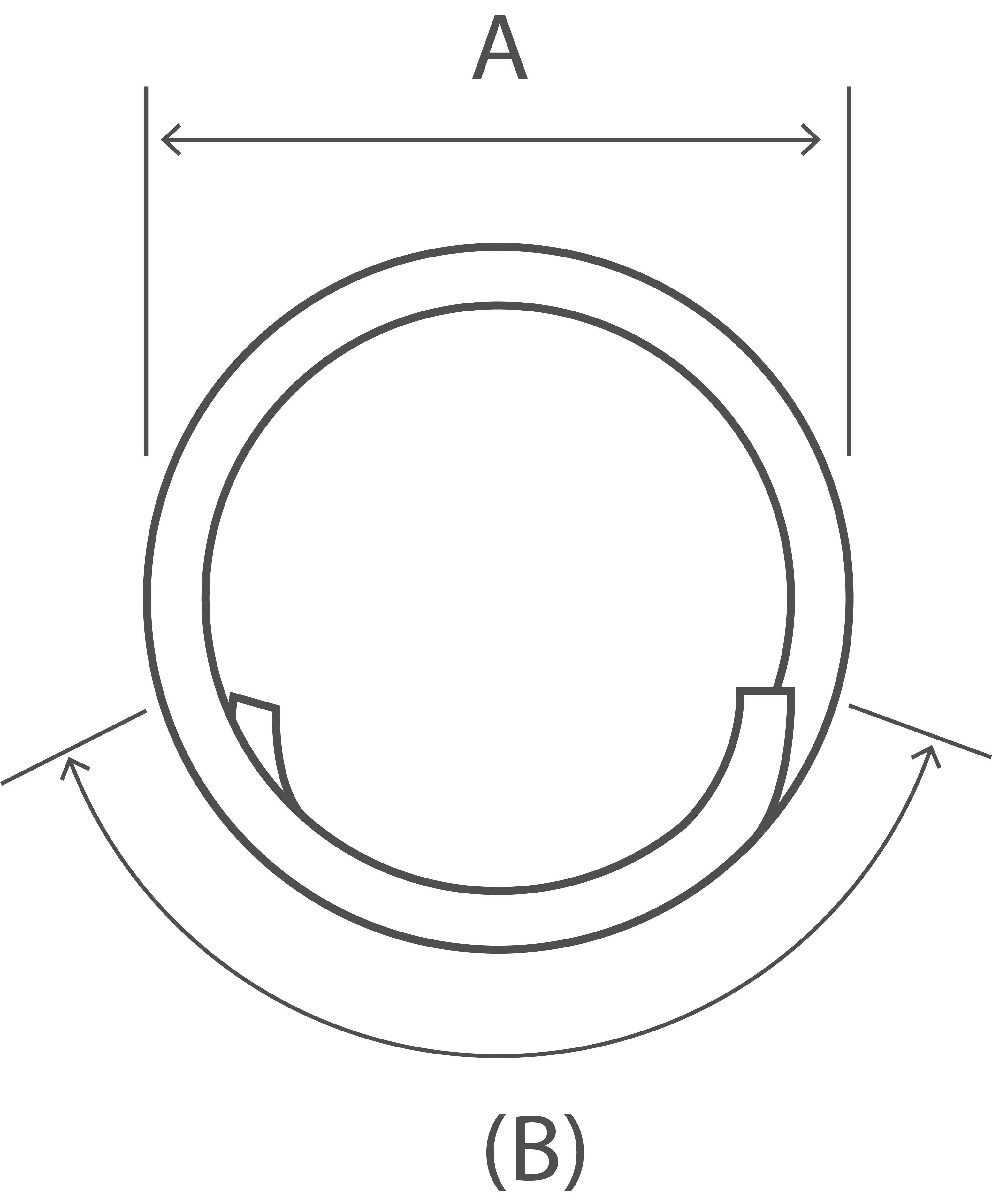
π(A - d) + B Where B is the lap |
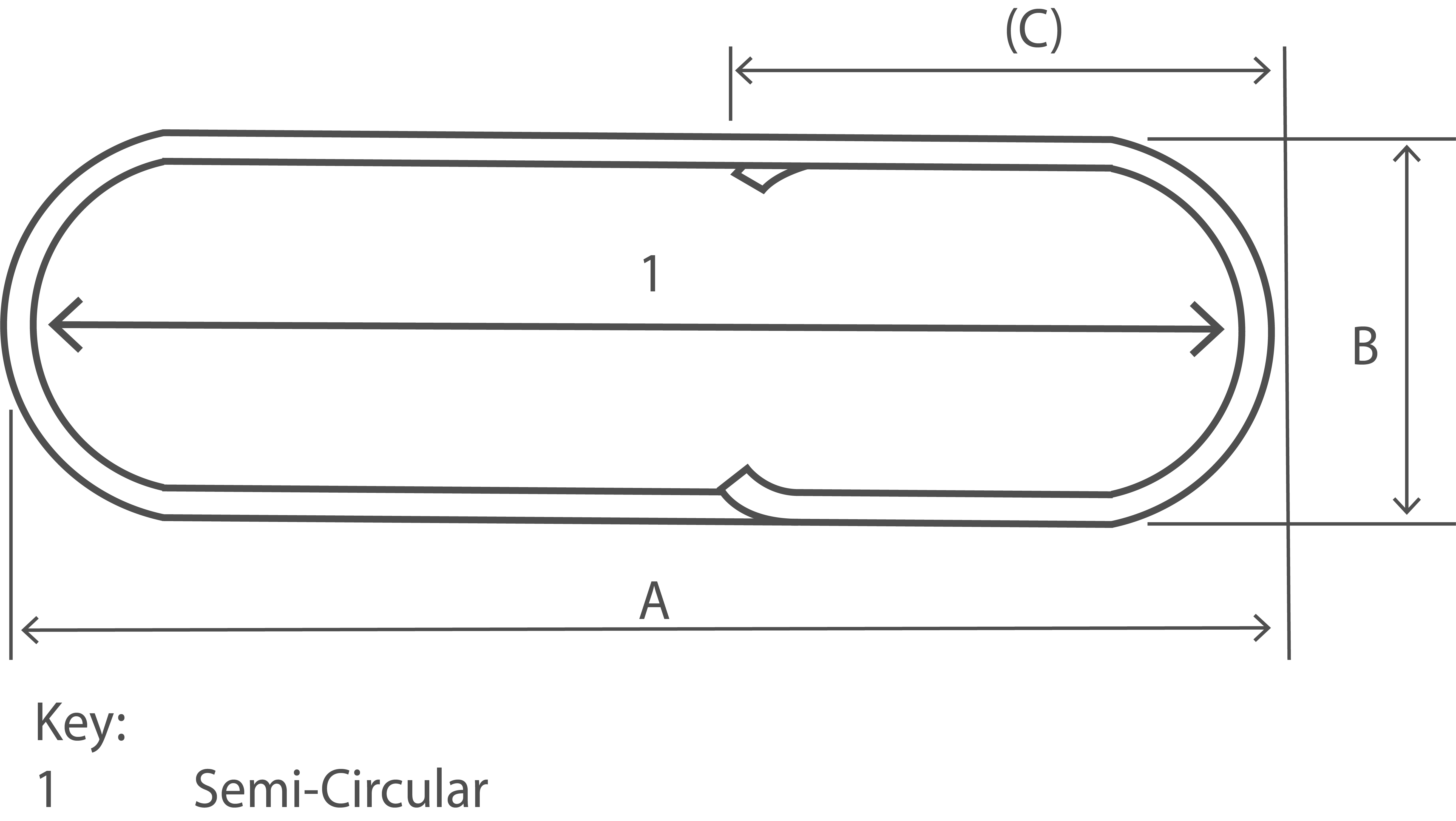
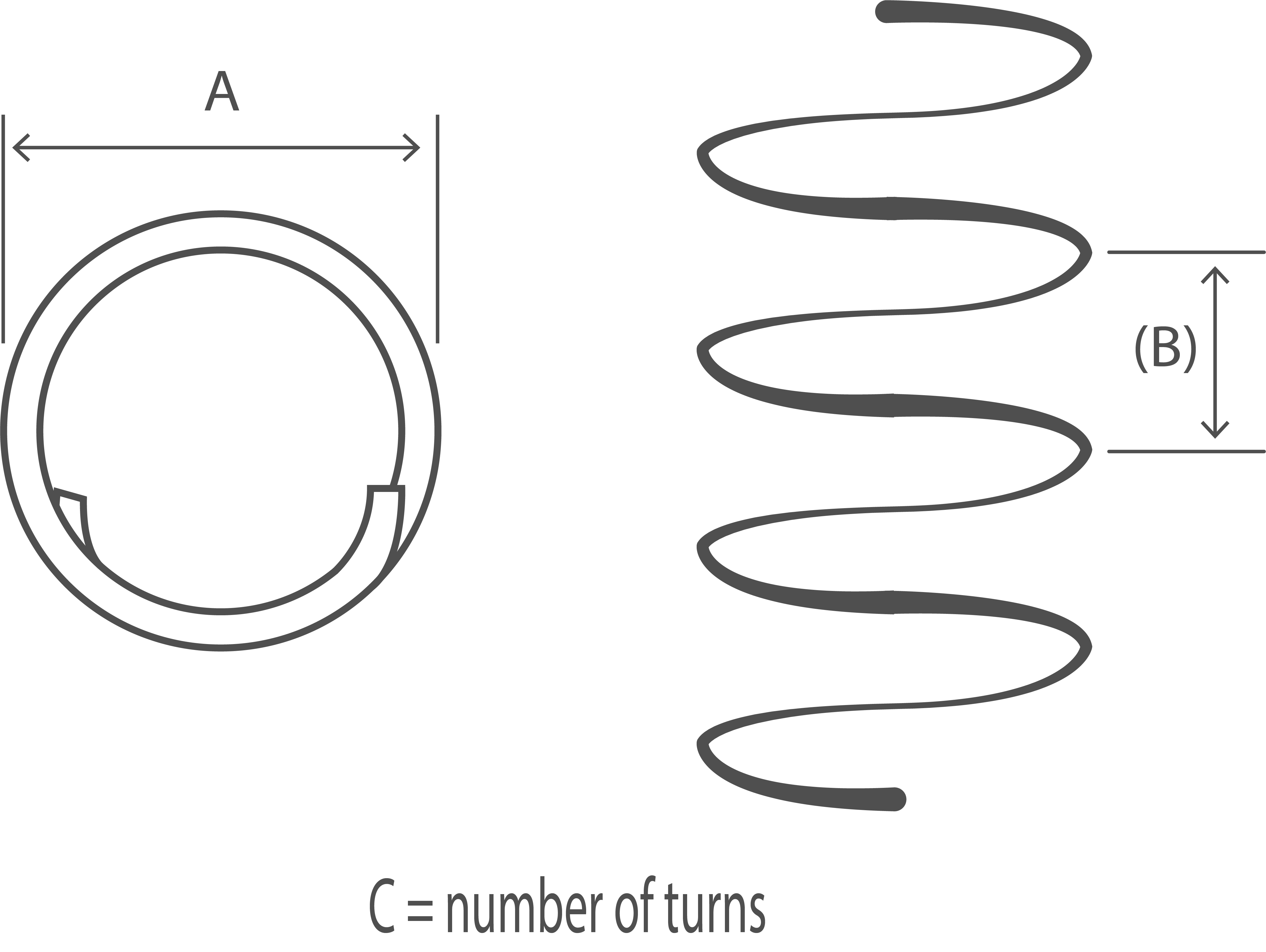
| Shape Code | 77 |
|---|---|
 |
|
| Total Length of bar. L measured along center line. |
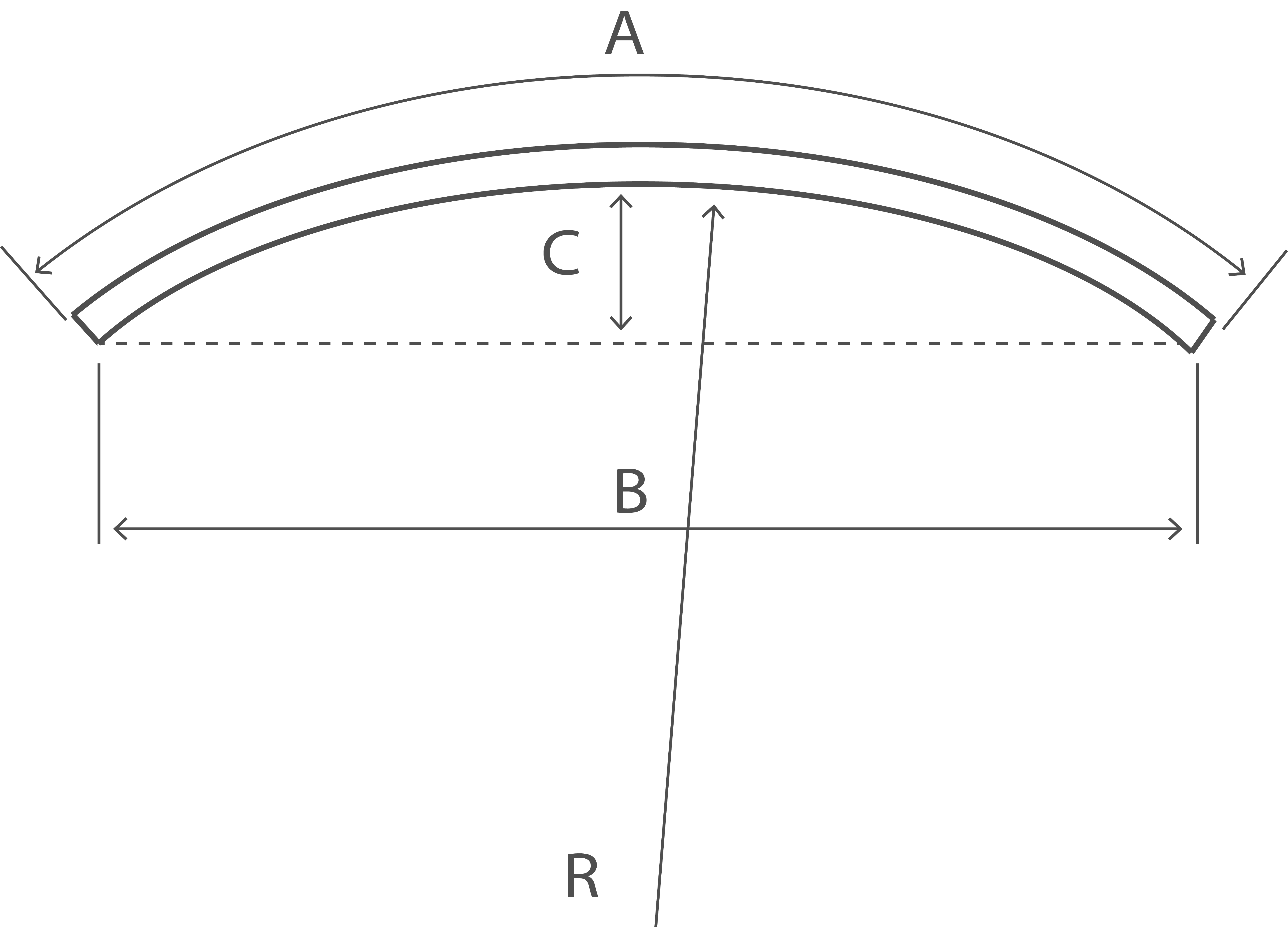
Cπ(A - d) Where B is greater than A/5 this equation no longer applies in which case the following formula may be used: L = C((π(A - d))2 + B2)0.5 |
| Shape Code | 98 |
|---|---|
 |
|
| Total Length of bar. L measured along center line. |
A + 2B + C + (D) -2r - 4d Isometric sketch |
| Shape Code | 99 |
|---|---|
|
All other shapes where standard shapes cannot be used. No other shape code number, form of designation or abbreviation shall be used in scheduling A dimensioned sketch shall be drawn over the dimension columns A to E. Every dimension shall be specified and the dimension that is to allow for permissible deviations shall be indicated in parenthesis, otherwise the fabricator is free to choose which dimension shall allow for tolerance |
|
| Total Length of bar. L measured along center line. |
To be calculated See Note 2. |
|
The values for minimum radius and end projection, r and P respectively (Minimum radius for scheduling and Minimum end projection) shall apply to all shape codes. The Dimensions in parentheses are the free dimensions, If a shape given in this table is required but a different dimension is to allow for the prossible deviations, the shape shall be drawn out and given the shape code 99 and the free dimension shall be indicated in parenthesis. The length of straight between two bends shall be at least 4d, where d is the diameter of the bar. NOTE 1: The length equations for shape codes 14, 15, 25, 26, 27, 28, 29, 34, 35, 36, and 46 are approximate and where the bend angle is greater than 45°, the length should be calculated more accurately allowing for the difference between the specified overall dimensions and the true length measured along the central axis of the bar. When the bending angles approach 90°, it is preferable to specify shape code 99 with a fully dimensioned sketch. NOTE 2: Five bends or more might be impractical within permitted tolerances. NOTE 3: For shapes with straight and curved lengths (e.g. shape codes 12, 13, 22, 33, and 47) the largest practical mandrel size for the production of a continuous curve is 400 mm. NOTE 4: Stock lengths are available in a limited number of lengths (e.g. 6m, 12m). Dimension A for shape code 01 should be regarded as indicative and used for the purpose of calculating total length. Actual delivery lengths should be by agreement with the supplier. Also, tolerances for shape code 01, stock lengths, shall be subject to the relevant product standard, e.g. BS 4449:2005. |